![7
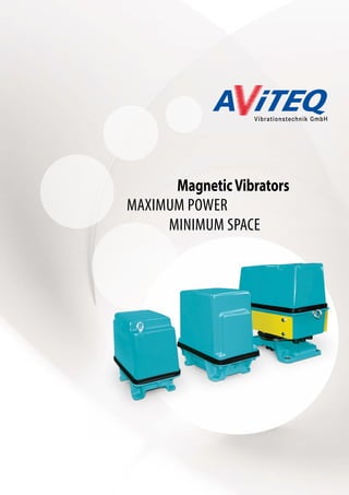
The vibration amplitudes suitable
for the different application and the
resulting material flow depend on the
vibration amplitudes in the particular
network.
STEP ONE: YOUR APPLICATION
7
VIBRATION FREQUENCY [Hz]
25 33 50 100
30 60 120
DOSING
CONVEYN
coarse SCREENING fine
COMPACTING
FEEDING/DISCHARGING
LOOSENING
DE-WATERING](https://image.slidesharecdn.com/aviteqmagneticvibrator-180806094410/85/AViTEQ-Magnetic-Vibrator-Brochure-7-320.jpg)
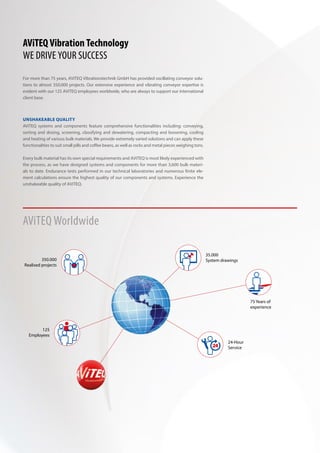
![PERFORMANCE GRAPHS FOR MAGNETIC VIBRATORS IN A 50 HZ NETWORK
10 100 200 500 1000 2000 Working weight Gn [kg]
2.5
2
1.5
1
0.5
0
VibrationamplitudeSn(mm)
Vibration frequency 50 Hz
1 MV B 50-4
2 MV C 50-4
3 MV C 50-4.2
4 MV D 50-4
5 MV E 50-4
6 MV ES 50-1
7 MV ES 50-1P
8 MV FS 50-2
9 MV G 50-2
10 MV FS 50-2P
11 MV G 50-11
12 MV GS 50-2P
13 MV H 50-2
| | | | | | | | | | | | | | | | | | |
1 2
3
4 5 6 7 8 12 13
9 10 11
4
3.5
3
2.5
2
1.5
1
0.5
0
VibrationamplitudeSn(mm)
Vibration frequency 33 Hz
1 MV ES 33-1
2 MV ES 33-1P
3 MV FS 33-1
4 MV FS 33-1P
5 MV G 33-1P
6 MV H 33-1P
1 2 3 4 5 6
| | | | | | | | | | | | | | | | | | |
10 100 200 500 1000 2000 Working weight Gn [kg]
4
3.5
3
2.5
2
1.5
1
0.5
0
VibrationamplitudeSn(mm)
Vibration frequency 25 Hz
1 MV C 25-4
2 MV D 25-4
3 MV E 25-4
1 2 3
| | | | | | | | | | | | | | | | | | |
10 100 200 500 1000 2000 Working weight Gn [kg]
0.7
0.6
0.5
0.4
0.3
0.2
0.1
0
VibrationamplitudeSn(mm)
Vibration frequency 100 Hz
1 MV 1/100-5
2 MV 6/100-6
3 MV C 100-41 2
3
| | | | | | | | | | | | | | | | | | | | | | |
0 1 2 5 10 20 Working weight Gn [kg]](https://image.slidesharecdn.com/aviteqmagneticvibrator-180806094410/85/AViTEQ-Magnetic-Vibrator-Brochure-8-320.jpg)
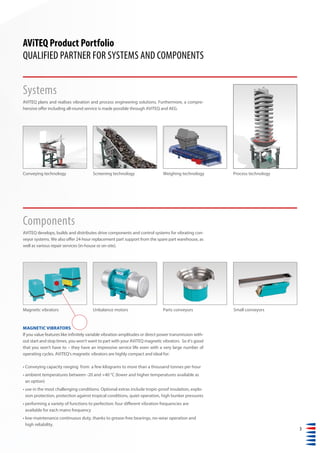
![9
PERFORMANCE GRAPHS FOR MAGNETIC VIBRATORS IN A 60 HZ NETWORK
4
3.5
3
2.5
2
1.5
1
VibrationamplitudeSn(mm)
Vibration frequency 30 Hz
1 MV C 30-4
2 MV D 30-3
3 MV E 30-3
4 MV F 30-4
1 2 3
| | | | | | | | | | | | | | | | | | |
10 100 200 500 1000 2000 Working weight Gn [kg]
4
3
2.5
2
1.5
1
0.5
0
VibrationamplitudeSn(mm)
Vibration frequency 40 Hz
1 MV ES 40-1
2 MV ES 40-1P
3 MV FS 40-1
4 MV FS 40-1P
5 MV GS 40-1P
1 2 3
| | | | | | | | |
100 1000 Working weight Gn [kg]
54
10 100 200 500 1000 2000 Working weight Gn [kg]
2
1.5
1
0.5
0
VibrationamplitudeSn(mm)
Vibration frequency 60 Hz
1 MV 12/60-3
2 MV B 60-4
3 MV C 60-4
4 MV C 60-4.1
5 MV D 60-4
6 MV E 60-4
7 MV ES 60-2
8 MV ES 60-2P
9 MV FS 60-3
10 MV FS 60-3P
11 MV GS 60-1P
| | | | | | | | | | | | | | | | | | |
3 5 6 7 8 11
9 10
0.1 1 2 5 10 Working weight Gn [kg]
0.5
0.4
0.3
0.2
0.1
0
VibrationamplitudeSn(mm)
Vibration frequency 120 Hz
1 MV 1/120-5
2 MV 6/120-4
| | | | | | | | | | | | | | | | | | |
1 2
21
4](https://image.slidesharecdn.com/aviteqmagneticvibrator-180806094410/85/AViTEQ-Magnetic-Vibrator-Brochure-9-320.jpg)
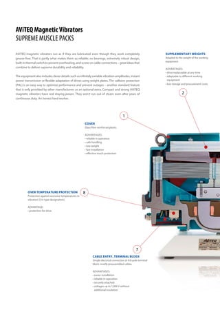
![MAGNETIC VIBRATORES IN A 50 HZ NETWORK
+ PAL integrated
– PAL not integrated
Type
Mains voltage
(controller input)
(+/-10%)
Protection to
EN 60529
Working weight range
[kg]
Vibration amplitude 1)
[mm]
Transport velocity 1)+2)
[cm/s]
Rated
current
Active
power 3)
[V] from to from to from to [A] [W]
MVC25-4 220 - 240 IP 55 14 40 3.65 2.15 18 8 4.80 40
380 - 420 IP 55 14 40 3.65 2.15 18 8 2.90 40
480 - 520 IP 55 14 40 3.65 2.15 18 8 2.20 40
MVD25-4 220 - 240 IP 55 35 150 3.40 1.20 16 3 8.00 50
380 - 420 IP 55 35 150 3.40 1.20 16 3 4.80 50
480 - 520 IP 55 35 150 3.40 1.20 16 3 3.80 50
MVE25-4 220 - 240 IP 55 70 250 3.80 1.50 19 4 14.00 100
380 - 420 IP 55 70 250 3.80 1.50 19 4 8.00 100
480 - 520 IP 55 70 250 3.80 1.50 19 4 6.10 100
33 Hz
MVES33-1 220 - 240 IP 55 90 300 2.80 1.15 20 4 17.0 150
380 - 420 IP 55 90 300 2.80 1.15 20 4 10.0 150
480 - 520 IP 55 90 300 2.80 1.15 20 4 10.0 150
MVES33-1P 220 - 240 IP 55 90 300 3.80 1.55 29 7 17.0 150
380 - 420 IP 55 90 300 3.80 1.55 29 7 10.0 150
480 - 520 IP 55 90 300 3.80 1.55 29 7 10.0 150
MVFS33-1 380 - 420 IP 55 190 600 2.60 1.05 18 3 15.0 250
480 - 520 IP 55 190 600 2.60 1.05 18 3 15.0 250
MVFS33-1P 380 - 420 IP 55 190 600 3.70 1.50 28 7 15.0 250
480 - 520 IP 55 190 600 3.70 1.50 28 7 15.0 250
MVG33-1P 380 - 420 IP 55 300 900 3.80 1.50 29 7 21.0 300
480 - 520 IP 55 300 900 3.80 1.50 29 7 17.0 300
MVH33-1P 380 - 420 IP 55 600 1800 3.80 1.50 29 7 37.5 900
480 - 520 IP 55 600 1800 3.80 1.50 29 7 30.0 900
Vibration frequency
25 Hz
1)+2) the transport velocity values relate to a minimum acceleration of about 1.8 g and a maximum acceleration of about 9 g.
1) For operation with an AViTEQ controller.
2) Theoretical transport velocity related to a defined reference bulk material (sand) with the following parameters: material density
1.6 t/m3
, grain size 3-10 mm, 8% product moisture with approximately cubic grains, 200 mm layer height, without bunker pressure,
with horizontal equipment installation.
3) The specified active power refers to vibrating conveyors without the influence of the transported goods.
The active power may increase by a factor of 5 depending on the type and amount of the load.
4) PAL is a sensor integrated into the magnetic vibrator; together with an appropriate controller, it forms a closed-loop control circuit for
the overall vibration amplitude, enabling performance optimisation.
All magnetic vibrators are sprayed in the standard colour RAL 5018.](https://image.slidesharecdn.com/aviteqmagneticvibrator-180806094410/85/AViTEQ-Magnetic-Vibrator-Brochure-10-320.jpg)
![11
d
b
c
f
e
a
PAL 4)
Possible
controller
Weight
[kg]
[kg] a b c d e Øf Screws
– BCE 42 210 125 420 180 280 11.5 M10
– B 42 210 125 420 180 280 11.5 M10
– B 42 210 125 420 180 280 11.5 M10
– BCE 61 210 125 450 220 335 11.5 M10
– BCE 61 210 125 450 220 335 11.5 M10
– B 61 210 125 450 220 335 11.5 M10
– BCE 110 300 190 485 255 425 18.0 M16
– BCE 110 300 190 485 225 425 18.0 M16
– BCE 110 300 190 485 255 425 18.0 M16
– CE 125 300 190 540 255 425 18.0 M16
– CE 125 300 190 540 255 425 18.0 M16
– CE 125 300 190 540 255 425 18.0 M16
+ DF 125 300 190 540 255 425 18.0 M16
+ DF 125 300 190 540 255 425 18.0 M16
+ DF 125 300 190 540 255 425 18.0 M16
– CE 250 350 240 640 340 545 22.0 M20
– CE 250 350 240 640 340 545 22.0 M20
+ DF 250 350 240 640 340 545 22.0 M20
+ DF 250 350 240 640 340 545 22.0 M20
+ DF 335 500 280 860 360 690 27.0 M24
+ DF 335 500 280 860 360 690 27.0 M24
+ DF 675 420 420 901 665 710 33.0 M30
+ DF 675 420 420 901 665 710 33.0 M30
Dimensions [mm]
A: Controller (Series SRA), analog, with compensation of possible mains voltage fluctuations.
B: Controller (Series SC), analog, with compensation of possible mains voltage fluctuations.
C: Controller (Series SA), analog, with compensation of possible mains voltage fluctuations, optional
control of effective vibration amplitude with external vibration amplitude sensor (PA ... ).
D: Controller (Series SA), analog, with compensation of possible mains voltage fluctuations, control
of internal overall vibration amplitude with integrated vibration amplitude sensor (PAL).
E: Controller (Series SD), digital, with compensation of possible mains voltage fluctuations,
optional control of effective vibration amplitude with external vibration amplitude sensor (PA ... ) in a 50 Hz network.
F: Controller (Series SD), digital, with compensation of possible mains voltage fluctuations,
control of internal overall vibration amplitude with integrated vibration amplitude sensor (PAL) in a 50 Hz network.](https://image.slidesharecdn.com/aviteqmagneticvibrator-180806094410/85/AViTEQ-Magnetic-Vibrator-Brochure-11-320.jpg)
![MAGNETIC VIBRATORES IN A 50 HZ NETWORK
Type
Mains voltage
(controller input)
(+/-10%)
Protection to
EN 60529
Working weight range
[kg]
Vibration amplitude 1)
[mm]
Transport velocity 1)+2)
[cm/s]
Rated
current
Active
power 3)
[V] from to from to from to [A] [W]
MV6/50-1 220 - 240 IP 55 2.5 6 0.95 0.60 9 3 0.45 25
MV12/50-3 220 - 240 IP 55 6 18 1.85 1.00 20 10 2.4 40
MVB50-4 220 - 240 IP 15 10 24 1.80 0.85 20 7 2.0 40
MVC50-4 220 - 240 IP 55 15 40 1.70 1.00 19 10 3.5 40
380 - 420 IP 55 15 40 1.70 1.00 19 10 2.1 40
480 - 520 IP 55 15 40 1.70 1.00 19 10 1.6 40
MVC50-4.2 220 - 240 IP 55 40 100 1.10 0.55 12 3 3.5 40
380 - 420 IP 55 40 100 1.10 0.55 12 3 2.1 40
480 - 520 IP 55 40 100 1.10 0.55 12 3 1.6 40
MVD50-4 220 - 240 IP 55 35 150 1.70 0.60 19 3 6.8 50
380 - 420 IP 55 35 150 1.70 0.60 19 3 4.0 50
480 - 520 IP 55 35 150 1.70 0.60 19 3 2.9 50
MVE50-4 220 - 240 IP 55 70 250 1.75 0.7 20 5 12.7 100
380 - 420 IP 55 70 250 1.75 0.7 20 5 6.8 100
480 - 520 IP 55 70 250 1.75 0.7 20 5 5.3 100
MVES50-1 220 - 240 IP 55 100 350 1.95 0.75 20 6 18.0 150
380 - 420 IP 55 100 350 1.95 0.75 20 6 11.0 150
480 - 520 IP 55 100 350 1.95 0.75 20 6 11.0 150
MVES50-1P 220 - 240 IP 55 125 350 2.05 0.90 20 8 18.0 150
380 - 420 IP 55 125 350 2.05 0.90 20 8 11.0 150
480 - 520 IP 55 125 350 2.05 0.90 20 8 11.0 150
MVFS50-2 380 - 420 IP 55 180 600 1.9 0.75 20 6 16.0 250
480 - 520 IP 55 180 600 1.90 0.75 20 6 16.0 250
MVFS50-2P 380 - 420 IP 55 180 600 2.25 0.90 20 8 16.0 250
480 - 520 IP 55 180 600 2.25 0.90 20 8 16.0 250
MVG50-2 380 - 420 IP 55 180 450 2.05 1.05 20 11 21.0 300
480 - 520 IP 55 180 450 2.05 1.05 20 11 16.0 300
MVG50-11 380 - 420 IP 25 165 450 2.35 1.10 20 12 21.0 300
480 - 520 IP 25 165 450 2.35 1.10 20 12 16.0 300
MVGS50-2P 380 - 420 IP 55 300 900 2.05 0.85 20 7 18.5 300
480 - 520 IP 55 300 900 2.05 0.85 20 7 16.0 300
MVH50-2 380 - 420 IP 55 520 1200 1.78 1.00 20 10 41.0 900
480 - 520 IP 55 520 1200 1.78 1.00 20 10 32.0 900
Vibration frequency
50 Hz
+ PAL integrated
– PAL not integrated
Legend: see pages 10/11](https://image.slidesharecdn.com/aviteqmagneticvibrator-180806094410/85/AViTEQ-Magnetic-Vibrator-Brochure-12-320.jpg)
![13
PAL 4) Possible
controller
Weight
[kg]
[kg] a b c d e Øf Screws
– A 7 240 — 265 154 140 11 M10
– AB 18 210 125 300 200 225 11.5 M10
– AB 14 Sidewise mounting 238 140 225 0 M10
– AB 39 210 125 420 180 280 11.5 M10
– B 39 210 125 420 180 280 11.5 M10
– B 39 210 125 420 180 280 11.5 M10
– AB 42 210 125 420 180 280 11.5 M10
– B 42 210 125 420 180 280 11.5 M10
– B 42 210 125 420 180 280 11.5 M10
– BCE 63 210 125 450 220 335 11.5 M10
– BCE 63 210 125 450 220 335 11.5 M10
– B 63 210 125 450 220 335 11.5 M10
– BCE 99 300 190 485 255 425 18.0 M16
– BCE 99 300 190 485 255 425 18.0 M16
– BCE 99 300 190 485 255 425 18.0 M16
– CE 125 300 190 540 255 425 18.0 M16
– BCE 125 300 190 540 255 425 18.0 M16
– BCE 125 300 190 540 255 425 18.0 M16
+ DF 125 300 190 540 255 425 18.0 M16
+ DF 125 300 190 540 255 425 18.0 M16
+ DF 125 300 190 540 255 425 18.0 M16
– CE 250 350 240 640 340 545 22.0 M20
– CE 250 350 240 640 340 545 22.0 M20
+ DF 250 350 240 640 340 545 22.0 M20
+ DF 250 350 240 640 340 545 22.0 M20
– CE 310 500 280 925 340 550 27.0 M24
– CE 310 500 280 925 340 550 27.0 M24
– CE 270 500 280 855 353 520 27.0 M24
– CE 270 500 280 855 353 520 27.0 M24
+ DF 395 500 280 860 395 680 27.0 M24
+ DF 395 500 280 860 395 680 27.0 M24
– CE 750 420 420 1000 570 665 33.0 M30
– CE 750 420 420 1000 570 665 33.0 M30
Dimensions [mm]
d
b
c
f
e
a](https://image.slidesharecdn.com/aviteqmagneticvibrator-180806094410/85/AViTEQ-Magnetic-Vibrator-Brochure-13-320.jpg)
![MAGNETIC VIBRATORES IN A 50 HZ NETWORK
Type
Mains voltage
(controller input)
(+/-10%)
Protection to
EN 60529
Working weight range
[kg]
Vibration amplitude 1)
[mm]
Transport velocity 1)+2)
[cm/s]
Rated
current
Active
power 3)
[V] from to from to from to [A] [W]
MV1/100-5 220 - 240 IP 55 0.2 3 0.53 0.23 Impact 0.3 10
MV6/100-6 220 - 240 IP 55 2.5 6 0.47 0.30 Impact 0.7 25
MVC100-4 220 - 240 IP 55 18.0 40 0.62 0.40 12 8 3.8 40
Magnetic vibrators in Ex design (Directive 2014/34/EU (ATEX))
25 Hz
eMVC25-4-01* 220 - 240 IP65 15 40 3.65 2.15 18 8 4.8 80
380 - 420 IP65 15 40 3.65 2.15 18 8 2.9 80
eMVD25-4-01* 220 - 240 IP65 35 150 3.40 1.20 16 3 8.0 110
380 - 420 IP65 35 150 3.40 1.20 16 3 4.8 110
eMVE25-4-01* 380 - 420 IP65 70 250 3.80 1.50 19 4 7.5 170
480 - 520 IP65 70 250 3.80 1.50 19 4 5.60 170
Magnetic vibrators in Ex design (Directive 2014/34/EU (ATEX))
50 Hz
eMVC50-4-01* 220 - 240 IP65 15 40 1.68 1.00 19 10 3.5 80
380 - 420 IP65 15 40 1.68 1.00 19 10 2.1 80
eMVC50-4.2-01* 220 - 240 IP65 40 100 1.08 0.55 11 3 3.5 80
380 - 420 IP65 40 100 1.08 0.55 11 3 2.1 80
eMVD50-4-01* 220 - 240 IP65 35 150 1.70 0.60 19 3 6.8 110
380 - 420 IP65 35 150 1.70 0.60 19 3 4.0 110
eMVE50-4-01* 220 - 240 IP65 70 250 1.68 0.68 19 5 12.2 170
380 - 420 IP65 70 250 1.68 0.68 19 5 6.2 170
480 - 520 IP65 70 250 1.68 0.68 19 5 5.0 170
Vibration frequency
100 Hz
*Standard cable entry: M20 x 1.5 (special cable entry: ..-02: M25x1.5)
+ PAL integrated
– PAL not integrated
1)+2) the transport velocity values relate to a minimum acceleration of about 1.8 g and a maximum acceleration of about 9 g.
1) For operation with an AViTEQ controller.
2) Theoretical transport velocity related to a defined reference bulk material (sand) with the following parameters: material density
1.6 t/m3
, grain size 3-10 mm, 8% product moisture with approximately cubic grains, 200 mm layer height, without bunker pressure,
with horizontal equipment installation.
3) The specified active power refers to vibrating conveyors without the influence of the transported goods.
The active power may increase by a factor of 5 depending on the type and amount of the load.
4) PAL is a sensor integrated into the magnetic vibrator; together with an appropriate controller, it forms a closed-loop control circuit for
the overall vibration amplitude, enabling performance optimisation.
All magnetic vibrators are sprayed in the standard colour RAL 5018.](https://image.slidesharecdn.com/aviteqmagneticvibrator-180806094410/85/AViTEQ-Magnetic-Vibrator-Brochure-14-320.jpg)
![15
PAL 4) Possible
controller
Weight
[kg]
[kg] a b c d e Øf Screws
– A 3.1 200 — 220 124 120 9.0 M8
– A 7 240 — 265 154 140 11.0 M10
– A 46 210 125 420 180 280 11.5 M10
– BCE 42 210 125 420 180 285 11.5 M10
– B 42 210 125 420 180 285 11.5 M10
– BCE 62 210 125 445 215 285 11.5 M10
– BCE 62 210 125 445 215 285 11.5 M10
– BCE 110 300 190 485 255 425 18.0 M16
– BCE 110 300 190 485 255 425 18.0 M16
– AB 40 210 125 420 180 285 11.5 M10
– B 40 210 125 420 180 285 11.5 M10
– AB 42 210 125 420 180 285 11.5 M10
– B 42 210 125 420 180 285 11.5 M10
– BCE 64 210 125 445 215 285 11.5 M10
– BCE 64 210 125 445 215 285 11.5 M10
– BCE 100 300 190 485 255 425 18.0 M16
– BCE 100 300 190 485 255 425 18.0 M16
– BCE 100 300 190 485 255 425 18.0 M16
Dimensions [mm]
A: Controller (Series SRA), analog, with compensation of possible mains voltage fluctuations.
B: Controller (Series SC), analog, with compensation of possible mains voltage fluctuations.
C: Controller (Series SA), analog, with compensation of possible mains voltage fluctuations, optional
control of effective vibration amplitude with external vibration amplitude sensor (PA ... ).
D: Controller (Series SA), analog, with compensation of possible mains voltage fluctuations, control
of internal overall vibration amplitude with integrated vibration amplitude sensor (PAL).
E: Controller (Series SD), digital, with compensation of possible mains voltage fluctuations,
optional control of effective vibration amplitude with external vibration amplitude sensor (PA ... ) in a 50 Hz network.
F: Controller (Series SD), digital, with compensation of possible mains voltage fluctuations,
control of internal overall vibration amplitude with integrated vibration amplitude sensor (PAL) in a 50 Hz network.
d
b
c
f
e
a](https://image.slidesharecdn.com/aviteqmagneticvibrator-180806094410/85/AViTEQ-Magnetic-Vibrator-Brochure-15-320.jpg)
![MAGNETIC VIBRATORES IN A 60 HZ NETWORK
Type
Mains voltage
(controller input)
(+/-10%)
Protection to
EN 60529
Working weight range
[kg]
Vibration amplitude 1)
[mm]
Transport velocity 1)+2)
[cm/s]
Rated
current
Active
power 3)
[V] from to from to from to [A] [W]
MVC30-4 220 - 240 IP 55 15 40 3.25 1.90 22 9 4.8 40
440 - 480 IP 55 15 40 3.25 1.90 22 9 2.4 40
MVD30-3 220 - 240 IP 55 36 70 3.05 2.00 20 10 8.0 50
380 - 420 IP 55 36 70 3.05 2.00 20 10 6.0 50
440 - 480 IP 55 36 70 3.05 2.00 20 10 4.4 50
MVE30-3 220 - 240 IP 55 55 120 3.55 2.15 25 11 14.0 100
380 - 420 IP 55 55 120 3.55 2.15 25 11 8.0 100
440 - 480 IP 55 55 120 3.55 2.15 25 11 7.0 100
MVF30-4 380 - 420 IP 55 180 600 3.05 1.20 20 4 18.0 250
440 - 480 IP 55 180 600 3.05 1.20 20 4 13.5 250
40 Hz
MVES40-1 380 - 420 IP 55 100 450 2.40 0.75 22 3 12.7 150
440 - 480 IP 55 100 450 2.40 0.75 22 3 10.0 150
MVES40-1P 380 - 420 IP 55 100 450 2.65 0.80 24 3 12.7 150
440 - 480 IP 55 100 450 2.65 0.80 24 3 10.0 150
MVFS40-1 380 - 420 IP 55 250 700 1.90 0.85 16 4 15.5 250
440 - 480 IP 55 250 700 1.90 0.85 16 4 13.5 250
MVFS40-1P 380 - 420 IP 55 290 700 2.00 1.00 18 5 15.5 250
440 - 480 IP 55 290 700 2.00 1.00 18 5 13.5 250
MVGS40-2P 440 - 480 IP 55 300 900 2.26 0.90 20 4 18.0 300
Vibration frequency
30 Hz
+ PAL integrted
– PAL not integrated
1)+2) the transport velocity values relate to a minimum acceleration of about 1.8 g and a maximum acceleration of about 9 g.
1) For operation with an AViTEQ controller.
2) Theoretical transport velocity related to a defined reference bulk material (sand) with the following parameters: material density
1.6 t/m3
, grain size 3-10 mm, 8% product moisture with approximately cubic grains, 200 mm layer height, without bunker pressure,
with horizontal equipment installation.
3) The specified active power refers to vibrating conveyors without the influence of the transported goods.
The active power may increase by a factor of 5 depending on the type and amount of the load.
4) PAL is a sensor integrated into the magnetic vibrator; together with an appropriate controller, it forms a closed-loop control circuit for
the overall vibration amplitude, enabling performance optimisation.
All magnetic vibrators are sprayed in the standard colour RAL 5018.](https://image.slidesharecdn.com/aviteqmagneticvibrator-180806094410/85/AViTEQ-Magnetic-Vibrator-Brochure-16-320.jpg)
![17
PAL 4) Possible
controller
Weight
[kg]
[kg] a b c d e Øf Screws
– BCE 40 210 125 420 180 280 11.5 M10
– BE 40 210 125 420 180 280 11.5 M10
– BCE 64 210 125 450 220 335 11.5 M10
– BCE 64 210 125 450 220 335 11.5 M10
– BCE 64 210 125 450 220 335 11.5 M10
– BCE 124 300 190 485 255 425 18.0 M16
– BCE 124 300 190 485 255 425 18.0 M16
– BCE 124 300 190 485 255 425 18.0 M16
– CE 250 350 240 640 340 545 22.0 M20
– BCE 250 350 240 640 340 545 22.0 M20
– CE 125 300 190 540 255 425 18.0 M16
– CE 125 300 190 540 255 425 18.0 M16
+ D 125 300 190 540 255 425 18.0 M16
+ D 125 300 190 540 255 425 18.0 M16
– CE 250 350 240 640 340 545 22.0 M20
– CE 250 350 240 640 340 545 22.0 M20
+ D 250 350 240 640 340 545 22.0 M20
+ D 250 350 240 640 340 545 22.0 M20
+ D 365 500 280 860 395 690 27.0 M24
Dimensions [mm]
A: Controller (Series SRA), analog, with compensation of possible mains voltage fluctuations.
B: Controller (Series SC), analog, with compensation of possible mains voltage fluctuations.
C: Controller (Series SA), analog, with compensation of possible mains voltage fluctuations, optional
control of effective vibration amplitude with external vibration amplitude sensor (PA ... ).
D: Controller (Series SA), analog, with compensation of possible mains voltage fluctuations, control
of internal overall vibration amplitude with integrated vibration amplitude sensor (PAL).
E: Controller (Series SD), digital, with compensation of possible mains voltage fluctuations,
optional control of effective vibration amplitude with external vibration amplitude sensor (PA ... ) in a 50 Hz network.
F: Controller (Series SD), digital, with compensation of possible mains voltage fluctuations,
control of internal overall vibration amplitude with integrated vibration amplitude sensor (PAL) in a 50 Hz network.
d
b
c
f
e
a](https://image.slidesharecdn.com/aviteqmagneticvibrator-180806094410/85/AViTEQ-Magnetic-Vibrator-Brochure-17-320.jpg)
![MAGNETIC VIBRATORES IN A 60 HZ NETWORK
Type
Mains voltage
(controller input)
(+/-10%)
Protection to
EN 60529
Working weight range
[kg]
Vibration amplitude 1)
[mm]
Transport velocity 1)+2)
[cm/s]
Rated
current
Active
power 3)
[V] from to from to from to [A] [W]
MV12/60-3 220 - 240 IP 55 10 20 1.40 0.90 16 11 2.70 40
MVB60-4 220 - 240 IP 15 12 20 1.38 0.90 16 11 2.00 40
MVC60-4 220 - 240 IP 55 15 40 1.55 0.90 16 11 3.80 40
380 - 420 IP 55 15 40 1.55 0.90 16 11 2.20 40
440 - 480 IP 55 15 40 1.55 0.90 16 11 1.90 40
MVC60-4.1 220 - 240 IP 55 40 100 0.90 0.45 11 3 3.80 40
380 - 420 IP 55 40 100 0.90 0.45 11 3 2.20 40
440 - 480 IP 55 40 100 0.90 0.45 11 3 1.90 40
MVD60-4 220 - 240 IP 55 35 150 1.55 0.55 16 4 6.80 50
380 - 420 IP 55 35 150 1.55 0.55 16 4 4.10 50
440 - 480 IP 55 35 150 1.55 0.55 16 4 4.00 50
MVE60-4 220 - 240 IP 55 70 250 1.25 0.50 16 3 11.4 100
380 - 420 IP 55 70 250 1.25 0.50 16 3 6.80 100
440 - 480 IP 55 70 250 1.25 0.50 16 3 5.80 100
MVES60-2 220 - 240 IP 55 110 500 1.38 0.40 16 2 18.0 150
380 - 420 IP 55 110 500 1.38 0.40 16 2 9.50 150
440 - 480 IP 55 110 500 1.38 0.40 16 2 8.00 150
MVES60-2P 220 - 240 IP 55 110 500 1.57 0.47 16 3 18.0 150
380 - 420 IP 55 110 500 1.57 0.47 16 3 9.50 150
440 - 480 IP 55 110 500 1.57 0.47 16 3 8.00 150
MVFS60-3 380 - 420 IP 55 210 600 1.36 0.60 16 5 13.5 250
440 - 480 IP 55 210 600 1.36 0.60 16 5 11.5 250
MVFS60-3P 380 - 420 IP 55 220 600 1.48 0.68 16 5 13.5 250
440 - 480 IP 55 220 600 1.48 0.68 16 5 11.5 250
MVGS60-1P 440 - 480 IP55 300 900 1.45 0.62 16 5 18.0 300
Vibration frequency
60 Hz
+ PAL integrated
– PAL not integrated
1)+2) the transport velocity values relate to a minimum acceleration of about 1.8 g and a maximum acceleration of about 9 g.
1) For operation with an AViTEQ controller.
2) Theoretical transport velocity related to a defined reference bulk material (sand) with the following parameters: material density
1.6 t/m3
, grain size 3-10 mm, 8% product moisture with approximately cubic grains, 200 mm layer height, without bunker pressure,
with horizontal equipment installation.
3) The specified active power refers to vibrating conveyors without the influence of the transported goods.
The active power may increase by a factor of 5 depending on the type and amount of the load.
4) PAL is a sensor integrated into the magnetic vibrator; together with an appropriate controller, it forms a closed-loop control circuit for
the overall vibration amplitude, enabling performance optimisation.
All magnetic vibrators are sprayed in the standard colour RAL 5018.](https://image.slidesharecdn.com/aviteqmagneticvibrator-180806094410/85/AViTEQ-Magnetic-Vibrator-Brochure-18-320.jpg)
![19
PAL 4) Possible
controller
Weight
[kg]
[kg] a b c d e Øf Screws
– AB 18 210 125 300 200 225 11.5 M10
– AB 17 Sidewise mounting 238 140 231 M10
– ABE 41 210 125 420 180 280 11.5 M10
– BE 41 210 125 420 180 280 11.5 M10
– BE 41 210 125 420 180 280 11.5 M10
– ABE 45 210 125 420 180 280 11.5 M10
– BE 45 210 125 420 180 280 11.5 M10
– BE 45 210 125 420 180 280 11.5 M10
– BCE 60 210 125 450 220 335 11.5 M10
– BCE 60 210 125 450 220 335 11.5 M10
– BCE 60 210 125 450 220 335 11.5 M10
– BCE 98 300 190 485 255 425 18.0 M16
– BCE 98 300 190 485 255 425 18.0 M16
– BCE 98 300 190 485 255 425 18.0 M16
– CE 125 300 190 540 255 425 18.0 M16
– BCE 125 300 190 540 255 425 18.0 M16
– BCE 125 300 190 540 255 425 18.0 M16
+ D 125 300 190 540 255 425 18.0 M16
+ D 125 300 190 540 255 425 18.0 M16
+ D 125 300 190 540 255 425 18.0 M16
– BCE 250 350 240 640 340 545 22.0 M20
– BCE 250 350 240 640 340 545 22.0 M20
+ D 250 350 240 640 340 545 22.0 M20
+ D 250 350 240 640 340 545 22.0 M20
+ D 415 500 280 860 395 680 27.0 M24
Dimensions [mm]
A: Controller (Series SRA), analog, with compensation of possible mains voltage fluctuations.
B: Controller (Series SC), analog, with compensation of possible mains voltage fluctuations.
C: Controller (Series SA), analog, with compensation of possible mains voltage fluctuations, optional
control of effective vibration amplitude with external vibration amplitude sensor (PA ... ).
D: Controller (Series SA), analog, with compensation of possible mains voltage fluctuations, control
of internal overall vibration amplitude with integrated vibration amplitude sensor (PAL).
E: Controller (Series SD), digital, with compensation of possible mains voltage fluctuations,
optional control of effective vibration amplitude with external vibration amplitude sensor (PA ... ) in a 50 Hz network.
F: Controller (Series SD), digital, with compensation of possible mains voltage fluctuations,
control of internal overall vibration amplitude with integrated vibration amplitude sensor (PAL) in a 50 Hz network.
d
b
c
f
e
a](https://image.slidesharecdn.com/aviteqmagneticvibrator-180806094410/85/AViTEQ-Magnetic-Vibrator-Brochure-19-320.jpg)
![+ PAL integrated
– PAL not integrated
1)+2) the transport velocity values relate to a minimum acceleration of about 1.8 g and a maximum acceleration of about 9 g.
1) For operation with an AViTEQ controller.
2) Theoretical transport velocity related to a defined reference bulk material (sand) with the following parameters: material density
1.6 t/m3
, grain size 3-10 mm, 8% product moisture with approximately cubic grains, 200 mm layer height, without bunker pressure,
with horizontal equipment installation.
3) The specified active power refers to vibrating conveyors without the influence of the transported goods.
The active power may increase by a factor of 5 depending on the type and amount of the load.
4) PAL is a sensor integrated into the magnetic vibrator; together with an appropriate controller, it forms a closed-loop control circuit for
the overall vibration amplitude, enabling performance optimisation.
All magnetic vibrators are sprayed in the standard colour RAL 5018.
MAGNETIC VIBRATORES IN A 60 HZ NETWORK
Type
Mains voltage
(controller input)
(+/-10%)
Protection to
EN 60529
Working weight range
[kg]
Vibration amplitude 1)
[mm]
Transport velocity 1)+2)
[cm/s]
Rated
current
Active
power 3)
[V] from to from to from to [A] [W]
MV1/120-5 220 - 240 IP 55 0.2 2 0.45 0.25 Impact 0.29 10
MV6/120-4 220 - 240 IP 55 2.5 6 0.47 0.30 Impact 0.6 25
Magnetic vibrators in Ex design (Directive 2014/34/EU (ATEX))
60 Hz
eMVC60-4-01* 220 - 240 IP65 15 40 1.48 0.85 16 10 3.8 80
440 - 480 IP65 15 40 1.48 0.85 16 10 1.8 80
Vibration frequency
120 Hz
*Standard cable entry: M20x1.5 (special cable entry: ..-02: M25x1.5)](https://image.slidesharecdn.com/aviteqmagneticvibrator-180806094410/85/AViTEQ-Magnetic-Vibrator-Brochure-20-320.jpg)
![21
A: Controller (Series SRA), analog, with compensation of possible mains voltage fluctuations.
B: Controller (Series SC), analog, with compensation of possible mains voltage fluctuations.
C: Controller (Series SA), analog, with compensation of possible mains voltage fluctuations, optional
control of effective vibration amplitude with external vibration amplitude sensor (PA ... ).
D: Controller (Series SA), analog, with compensation of possible mains voltage fluctuations, control
of internal overall vibration amplitude with integrated vibration amplitude sensor (PAL).
E: Controller (Series SD), digital, with compensation of possible mains voltage fluctuations,
optional control of effective vibration amplitude with external vibration amplitude sensor (PA ... ) in a 50 Hz network.
F: Controller (Series SD), digital, with compensation of possible mains voltage fluctuations,
control of internal overall vibration amplitude with integrated vibration amplitude sensor (PAL) in a 50 Hz network.
PAL 4) Possible
controller
Weight
[kg]
[kg] a b c d e Øf Screws
– A 3.1 200 — 220 124 120 9.0 M8
– A 7 240 — 265 154 140 11.0 M10
– AB 42 210 125 420 180 285 11.5 M10
– B 42 210 125 420 180 285 11.5 M10
Dimensions [mm]
d
b
c
f
e
a](https://image.slidesharecdn.com/aviteqmagneticvibrator-180806094410/85/AViTEQ-Magnetic-Vibrator-Brochure-21-320.jpg)
![23
Characteristics SRA(E)... SC(E)... SA(E)... SD(E)...
Vibrator current, maximum 6 A 15 A 25 or 43 A 25, 50 or 100 A
Mains voltage in 50/60 Hz networks
Special voltages available on request
105...115 V 220...240 V 220...240 V1
220...240 V1
220...240 V 380...420 V 380...420 V 380...420 V
440...480 V 440...480 V 440...480 V
500...520 V 460...500 V 480...520 V
Vibration frequency in 50 Hz network 50 or 100 Hz 25 or 50 Hz 25, 33 or 50 Hz 25, 33 or 50 Hz
Vibration frequency in 60 Hz network 60 or 120 Hz 30 or 60 Hz 30, 40 or 60 Hz 30,40 or 60 Hz
Signal processing analog analog analog digital
Voltage control + + + +
Vibration amplitude control with collision monitoring +
Limiting control with collision monitoring +
Vibration amplitude control + +
Temperature monitoring for magnetic vibrator directly connectable + +
External reference variables directly connectable
(0-10 V DC; 4-20 mA or 0-20 mA)
+ + + +
Set value switchable between potentiometer (local) and
external reference variable
(+)2
+ + +
Vibration amplitude approximately proportional to setpoint + + + +
External actual value display connectable + +
Enable (switch on/off) via Switch Switch Switch Switch
Opto-coupler Opto-coupler Button Button
Voltage signal
+24 V DC
Voltage signal
+24 V DC
Opto-coupler Opto-coupler
Integrated status relay 1 relay 1 relay 1 relay 2 relays
Display of operating status via Illuminated
power switch
2 LEDs 7 LEDs 2 LEDs and
4-digit display
Actual value output
Maximum value at maximum vibration amplitude
+ 10.0 V DC + 8.0 V DC3
+10.0 V DC
Master/Slave integrated (for multiple drive) +
Reversing mode integrated +
Powersupplyoutput + 5.0 V DC + 5.0 V DC
Configuration adjustable with Trimmer Trimmer Trimmer
Jumper Dip switch Keypad
Operating data for multiple AVITEQ magnetic vibrators
stored and selectable
+
Open frame version (E),
height x width x depth [mm]
125x112x102 200x62x190 200x230x140 388x150x350
Version with housing (standard),
height x width x depth [mm]
170x120x92 300x300x210 300x380x155 (25A) 600x380x350
380x380x210 (43A)
Controllers
CONNECTIONS AND COMMISSIONING
+ integrated
1) 25 A Version
2) Only possible for 0-10 V DC
3) Adjustable via software. In addition, for voltages, the lower limit can be increased via software from 0 to +2.0 V](https://image.slidesharecdn.com/aviteqmagneticvibrator-180806094410/85/AViTEQ-Magnetic-Vibrator-Brochure-23-320.jpg)

AViTEQ Magnetic Vibrator Brochure
- 2. AViTEQ Vibration Technology WE DRIVE YOUR SUCCESS For more than 75 years, AViTEQ Vibrationstechnik GmbH has provided oscillating conveyor solu- tions to almost 350,000 projects. Our extensive experience and vibrating conveyor expertise is evident with our 125 AViTEQ employees worldwide, who are always to support our international client base. AViTEQ Worldwide 350.000 Realised projects 125 Employees 35.000 System drawings 24-Hour Service 75 Years of experience UNSHAKEABLE QUALITY AViTEQ systems and components feature comprehensive functionalities including: conveying, sorting and dosing, screening, classifying and dewatering, compacting and loosening, cooling and heating of various bulk materials. We provide extremely varied solutions and can apply these functionalities to suit small pills and coffee beans, as well as rocks and metal pieces weighing tons. Every bulk material has its own special requirements and AViTEQ is most likely experienced with the process, as we have designed systems and components for more than 3,600 bulk materi- als to date. Endurance tests performed in our technical laboratories and numerous finite ele- ment calculations ensure the highest quality of our components and systems. Experience the unshakeable quality of AViTEQ.
- 3. 3 Parts conveyors Small conveyors MAGNETIC VIBRATORS If you value features like infinitely variable vibration amplitudes or direct power transmission with- out start and stop times, you won‘t want to part with your AViTEQ magnetic vibrators. So it‘s good that you won‘t have to – they have an impressive service life even with a very large number of operating cycles. AViTEQ‘s magnetic vibrators are highly compact and ideal for: • Conveying capacity ranging from a few kilograms to more than a thousand tonnes per hour • ambient temperatures between -20 and +40 °C (lower and higher temperatures available as an option) • use in the most challenging conditions. Optional extras include tropic-proof insulation, explo- sion protection, protection against tropical conditions, quiet operation, high bunker pressures • performing a variety of functions to perfection: four different vibration frequencies are available for each mains frequency • low-maintenance continuous duty, thanks to grease-free bearings, no-wear operation and high reliability. Systems AViTEQ plans and realises vibration and process engineering solutions. Furthermore, a compre- hensive offer including all-round service is made possible through AViTEQ and AEG. Components AViTEQ develops, builds and distributes drive components and control systems for vibrating con- veyor systems. We also offer 24-hour replacement part support from the spare part warehouse, as well as various repair services (in-house or on-site). Screening technologyConveying technology Weighing technology AViTEQ Product Portfolio QUALIFIED PARTNER FOR SYSTEMS AND COMPONENTS Process technology Unbalance motorsMagnetic vibrators
- 4. AViTEQ Magnetic Vibrators SUPREME MUSCLE PACKS AViTEQ magnetic vibrators run as if they are lubricated even though they work completely grease-free. That is partly what makes them so reliable: no bearings, extremely robust design, built-in thermal switch to prevent overheating, and screw-on cable connections – great ideas that combine to deliver supreme durability and reliability. The equipment also includes clever details such as infinitely variable vibration amplitudes, instant power transmission or flexible adaptation of drives using weight plates. The collision protection (PAL) is an easy way to optimise performance and prevent outages – another standard feature that is only provided by other manufacturers as an optional extra. Compact and strong AViTEQ magnetic vibrators have real staying power. They won‘t run out of steam even after years of continuous duty. An honest hard-worker. CABLE ENTRY, TERMINAL BLOCK Simple electrical connection at 4/6-pole terminal block; mostly preassembled cables. ADVANTAGES: • easier installation • reliable in operation • securely attached • voltages up to 1,000 V without additional insulation SUPPLEMENTARY WEIGHTS Adapted to the weight of the working equipment. ADVANTAGES: • drive replaceable at any time • adaptable to different working equipment • low storage and procurement costs OVER TEMPERATURE PROTECTION Protection against excessive temperatures in vibrators (S in type designation). ADVANTAGE: • protection for drive 1 2 7 8 COVER Glass fibre reinforced plastic. ADVANTAGES: • reliable in operation • safe handling • low weight • fast installation • effective touch protection
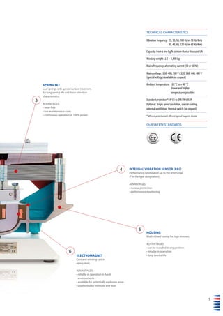
- 5. 5 TECHNICAL CHARACTERISTICS Vibration frequency: 25, 33, 50, 100 Hz im 50 Hz-Netz 30, 40, 60, 120 Hz im 60 Hz-Netz Capacity: from a few kg/h to more than a thousand t/h Working weight: 2.5 – 1,800 kg Mains frequency: alternating current (50 or 60 Hz) Mains voltage: 230, 400, 500 V / 220, 380, 440, 480 V (special voltages available on request) Ambient temperature: -20 °C to + 40 °C (lower and higher temperatures possible) Standard protection*: IP 55 to DIN EN 60529 Optional: tropic-proof insulation, special coating, external ventilation, thermal switch (on request) OUR SAFETY STANDARDS * different protection with different types of magnetic vibrator INTERNAL VIBRATION SENSOR (PAL) Performance optimisation up to the limit range (P in the type designation). ADVANTAGES: • outage protection • performance monitoring HOUSING Multi-ribbed casing for high stresses. ADVANTAGES: • can be installed in any position • reliable in operation • long service life SPRING SET Leaf springs with special surface treatment for long service life and linear vibration characteristics. ADVANTAGES: • wear-free • low maintenance costs • continuous operation at 100% power ELECTROMAGNET Core and winding cast in epoxy resin. ADVANTAGES: • reliable in operation in harsh environments • available for potentially explosive areas • unaffected by moisture and dust 3 4 5 6
- 6. Design and Choice of Motor THREE STEPS TO THE RIGHT MAGNETIC VIBRATOR SELECTION 1. Determine your application and the mains frequency, and obtain the vibration frequency from the bar chart. 2. In the case of drives for vibrating equipment (trough conveyors, tubular conveyors, screens, de-watering devices, helical conveyors, vibrating tables, etc.), selection is primarily based on the „working weight“. The starting point is the weight of the vibrating conveyor without the magnetic vibrator and disregarding the goods on the conveyor. In the case of bunker vibrators (external vibrators, silos, bunkers, hoppers, shake-out grids, fall pipes, filters and filling machines), we recommend that AViTEQ selects the best magnetic vibrator/impact vibrator for you. 3. Use the vibration frequency, the mains voltage and the working weight range or working weight to select the right magnetic vibrator type from the graphs below. There is a lot of technical information available, but it is always best to get AViTEQ‘s help with selection. Choosing the best magnetic vibrator depends on many different factors. And that is a job for experts.
- 7. 7 The vibration amplitudes suitable for the different application and the resulting material flow depend on the vibration amplitudes in the particular network. STEP ONE: YOUR APPLICATION 7 VIBRATION FREQUENCY [Hz] 25 33 50 100 30 60 120 DOSING CONVEYN coarse SCREENING fine COMPACTING FEEDING/DISCHARGING LOOSENING DE-WATERING
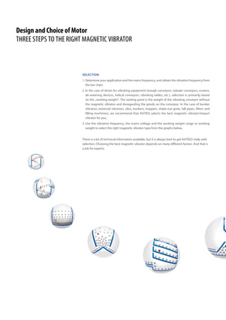
- 8. PERFORMANCE GRAPHS FOR MAGNETIC VIBRATORS IN A 50 HZ NETWORK 10 100 200 500 1000 2000 Working weight Gn [kg] 2.5 2 1.5 1 0.5 0 VibrationamplitudeSn(mm) Vibration frequency 50 Hz 1 MV B 50-4 2 MV C 50-4 3 MV C 50-4.2 4 MV D 50-4 5 MV E 50-4 6 MV ES 50-1 7 MV ES 50-1P 8 MV FS 50-2 9 MV G 50-2 10 MV FS 50-2P 11 MV G 50-11 12 MV GS 50-2P 13 MV H 50-2 | | | | | | | | | | | | | | | | | | | 1 2 3 4 5 6 7 8 12 13 9 10 11 4 3.5 3 2.5 2 1.5 1 0.5 0 VibrationamplitudeSn(mm) Vibration frequency 33 Hz 1 MV ES 33-1 2 MV ES 33-1P 3 MV FS 33-1 4 MV FS 33-1P 5 MV G 33-1P 6 MV H 33-1P 1 2 3 4 5 6 | | | | | | | | | | | | | | | | | | | 10 100 200 500 1000 2000 Working weight Gn [kg] 4 3.5 3 2.5 2 1.5 1 0.5 0 VibrationamplitudeSn(mm) Vibration frequency 25 Hz 1 MV C 25-4 2 MV D 25-4 3 MV E 25-4 1 2 3 | | | | | | | | | | | | | | | | | | | 10 100 200 500 1000 2000 Working weight Gn [kg] 0.7 0.6 0.5 0.4 0.3 0.2 0.1 0 VibrationamplitudeSn(mm) Vibration frequency 100 Hz 1 MV 1/100-5 2 MV 6/100-6 3 MV C 100-41 2 3 | | | | | | | | | | | | | | | | | | | | | | | 0 1 2 5 10 20 Working weight Gn [kg]
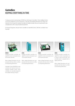
- 9. 9 PERFORMANCE GRAPHS FOR MAGNETIC VIBRATORS IN A 60 HZ NETWORK 4 3.5 3 2.5 2 1.5 1 VibrationamplitudeSn(mm) Vibration frequency 30 Hz 1 MV C 30-4 2 MV D 30-3 3 MV E 30-3 4 MV F 30-4 1 2 3 | | | | | | | | | | | | | | | | | | | 10 100 200 500 1000 2000 Working weight Gn [kg] 4 3 2.5 2 1.5 1 0.5 0 VibrationamplitudeSn(mm) Vibration frequency 40 Hz 1 MV ES 40-1 2 MV ES 40-1P 3 MV FS 40-1 4 MV FS 40-1P 5 MV GS 40-1P 1 2 3 | | | | | | | | | 100 1000 Working weight Gn [kg] 54 10 100 200 500 1000 2000 Working weight Gn [kg] 2 1.5 1 0.5 0 VibrationamplitudeSn(mm) Vibration frequency 60 Hz 1 MV 12/60-3 2 MV B 60-4 3 MV C 60-4 4 MV C 60-4.1 5 MV D 60-4 6 MV E 60-4 7 MV ES 60-2 8 MV ES 60-2P 9 MV FS 60-3 10 MV FS 60-3P 11 MV GS 60-1P | | | | | | | | | | | | | | | | | | | 3 5 6 7 8 11 9 10 0.1 1 2 5 10 Working weight Gn [kg] 0.5 0.4 0.3 0.2 0.1 0 VibrationamplitudeSn(mm) Vibration frequency 120 Hz 1 MV 1/120-5 2 MV 6/120-4 | | | | | | | | | | | | | | | | | | | 1 2 21 4
- 10. MAGNETIC VIBRATORES IN A 50 HZ NETWORK + PAL integrated – PAL not integrated Type Mains voltage (controller input) (+/-10%) Protection to EN 60529 Working weight range [kg] Vibration amplitude 1) [mm] Transport velocity 1)+2) [cm/s] Rated current Active power 3) [V] from to from to from to [A] [W] MVC25-4 220 - 240 IP 55 14 40 3.65 2.15 18 8 4.80 40 380 - 420 IP 55 14 40 3.65 2.15 18 8 2.90 40 480 - 520 IP 55 14 40 3.65 2.15 18 8 2.20 40 MVD25-4 220 - 240 IP 55 35 150 3.40 1.20 16 3 8.00 50 380 - 420 IP 55 35 150 3.40 1.20 16 3 4.80 50 480 - 520 IP 55 35 150 3.40 1.20 16 3 3.80 50 MVE25-4 220 - 240 IP 55 70 250 3.80 1.50 19 4 14.00 100 380 - 420 IP 55 70 250 3.80 1.50 19 4 8.00 100 480 - 520 IP 55 70 250 3.80 1.50 19 4 6.10 100 33 Hz MVES33-1 220 - 240 IP 55 90 300 2.80 1.15 20 4 17.0 150 380 - 420 IP 55 90 300 2.80 1.15 20 4 10.0 150 480 - 520 IP 55 90 300 2.80 1.15 20 4 10.0 150 MVES33-1P 220 - 240 IP 55 90 300 3.80 1.55 29 7 17.0 150 380 - 420 IP 55 90 300 3.80 1.55 29 7 10.0 150 480 - 520 IP 55 90 300 3.80 1.55 29 7 10.0 150 MVFS33-1 380 - 420 IP 55 190 600 2.60 1.05 18 3 15.0 250 480 - 520 IP 55 190 600 2.60 1.05 18 3 15.0 250 MVFS33-1P 380 - 420 IP 55 190 600 3.70 1.50 28 7 15.0 250 480 - 520 IP 55 190 600 3.70 1.50 28 7 15.0 250 MVG33-1P 380 - 420 IP 55 300 900 3.80 1.50 29 7 21.0 300 480 - 520 IP 55 300 900 3.80 1.50 29 7 17.0 300 MVH33-1P 380 - 420 IP 55 600 1800 3.80 1.50 29 7 37.5 900 480 - 520 IP 55 600 1800 3.80 1.50 29 7 30.0 900 Vibration frequency 25 Hz 1)+2) the transport velocity values relate to a minimum acceleration of about 1.8 g and a maximum acceleration of about 9 g. 1) For operation with an AViTEQ controller. 2) Theoretical transport velocity related to a defined reference bulk material (sand) with the following parameters: material density 1.6 t/m3 , grain size 3-10 mm, 8% product moisture with approximately cubic grains, 200 mm layer height, without bunker pressure, with horizontal equipment installation. 3) The specified active power refers to vibrating conveyors without the influence of the transported goods. The active power may increase by a factor of 5 depending on the type and amount of the load. 4) PAL is a sensor integrated into the magnetic vibrator; together with an appropriate controller, it forms a closed-loop control circuit for the overall vibration amplitude, enabling performance optimisation. All magnetic vibrators are sprayed in the standard colour RAL 5018.
- 11. 11 d b c f e a PAL 4) Possible controller Weight [kg] [kg] a b c d e Øf Screws – BCE 42 210 125 420 180 280 11.5 M10 – B 42 210 125 420 180 280 11.5 M10 – B 42 210 125 420 180 280 11.5 M10 – BCE 61 210 125 450 220 335 11.5 M10 – BCE 61 210 125 450 220 335 11.5 M10 – B 61 210 125 450 220 335 11.5 M10 – BCE 110 300 190 485 255 425 18.0 M16 – BCE 110 300 190 485 225 425 18.0 M16 – BCE 110 300 190 485 255 425 18.0 M16 – CE 125 300 190 540 255 425 18.0 M16 – CE 125 300 190 540 255 425 18.0 M16 – CE 125 300 190 540 255 425 18.0 M16 + DF 125 300 190 540 255 425 18.0 M16 + DF 125 300 190 540 255 425 18.0 M16 + DF 125 300 190 540 255 425 18.0 M16 – CE 250 350 240 640 340 545 22.0 M20 – CE 250 350 240 640 340 545 22.0 M20 + DF 250 350 240 640 340 545 22.0 M20 + DF 250 350 240 640 340 545 22.0 M20 + DF 335 500 280 860 360 690 27.0 M24 + DF 335 500 280 860 360 690 27.0 M24 + DF 675 420 420 901 665 710 33.0 M30 + DF 675 420 420 901 665 710 33.0 M30 Dimensions [mm] A: Controller (Series SRA), analog, with compensation of possible mains voltage fluctuations. B: Controller (Series SC), analog, with compensation of possible mains voltage fluctuations. C: Controller (Series SA), analog, with compensation of possible mains voltage fluctuations, optional control of effective vibration amplitude with external vibration amplitude sensor (PA ... ). D: Controller (Series SA), analog, with compensation of possible mains voltage fluctuations, control of internal overall vibration amplitude with integrated vibration amplitude sensor (PAL). E: Controller (Series SD), digital, with compensation of possible mains voltage fluctuations, optional control of effective vibration amplitude with external vibration amplitude sensor (PA ... ) in a 50 Hz network. F: Controller (Series SD), digital, with compensation of possible mains voltage fluctuations, control of internal overall vibration amplitude with integrated vibration amplitude sensor (PAL) in a 50 Hz network.
- 12. MAGNETIC VIBRATORES IN A 50 HZ NETWORK Type Mains voltage (controller input) (+/-10%) Protection to EN 60529 Working weight range [kg] Vibration amplitude 1) [mm] Transport velocity 1)+2) [cm/s] Rated current Active power 3) [V] from to from to from to [A] [W] MV6/50-1 220 - 240 IP 55 2.5 6 0.95 0.60 9 3 0.45 25 MV12/50-3 220 - 240 IP 55 6 18 1.85 1.00 20 10 2.4 40 MVB50-4 220 - 240 IP 15 10 24 1.80 0.85 20 7 2.0 40 MVC50-4 220 - 240 IP 55 15 40 1.70 1.00 19 10 3.5 40 380 - 420 IP 55 15 40 1.70 1.00 19 10 2.1 40 480 - 520 IP 55 15 40 1.70 1.00 19 10 1.6 40 MVC50-4.2 220 - 240 IP 55 40 100 1.10 0.55 12 3 3.5 40 380 - 420 IP 55 40 100 1.10 0.55 12 3 2.1 40 480 - 520 IP 55 40 100 1.10 0.55 12 3 1.6 40 MVD50-4 220 - 240 IP 55 35 150 1.70 0.60 19 3 6.8 50 380 - 420 IP 55 35 150 1.70 0.60 19 3 4.0 50 480 - 520 IP 55 35 150 1.70 0.60 19 3 2.9 50 MVE50-4 220 - 240 IP 55 70 250 1.75 0.7 20 5 12.7 100 380 - 420 IP 55 70 250 1.75 0.7 20 5 6.8 100 480 - 520 IP 55 70 250 1.75 0.7 20 5 5.3 100 MVES50-1 220 - 240 IP 55 100 350 1.95 0.75 20 6 18.0 150 380 - 420 IP 55 100 350 1.95 0.75 20 6 11.0 150 480 - 520 IP 55 100 350 1.95 0.75 20 6 11.0 150 MVES50-1P 220 - 240 IP 55 125 350 2.05 0.90 20 8 18.0 150 380 - 420 IP 55 125 350 2.05 0.90 20 8 11.0 150 480 - 520 IP 55 125 350 2.05 0.90 20 8 11.0 150 MVFS50-2 380 - 420 IP 55 180 600 1.9 0.75 20 6 16.0 250 480 - 520 IP 55 180 600 1.90 0.75 20 6 16.0 250 MVFS50-2P 380 - 420 IP 55 180 600 2.25 0.90 20 8 16.0 250 480 - 520 IP 55 180 600 2.25 0.90 20 8 16.0 250 MVG50-2 380 - 420 IP 55 180 450 2.05 1.05 20 11 21.0 300 480 - 520 IP 55 180 450 2.05 1.05 20 11 16.0 300 MVG50-11 380 - 420 IP 25 165 450 2.35 1.10 20 12 21.0 300 480 - 520 IP 25 165 450 2.35 1.10 20 12 16.0 300 MVGS50-2P 380 - 420 IP 55 300 900 2.05 0.85 20 7 18.5 300 480 - 520 IP 55 300 900 2.05 0.85 20 7 16.0 300 MVH50-2 380 - 420 IP 55 520 1200 1.78 1.00 20 10 41.0 900 480 - 520 IP 55 520 1200 1.78 1.00 20 10 32.0 900 Vibration frequency 50 Hz + PAL integrated – PAL not integrated Legend: see pages 10/11
- 13. 13 PAL 4) Possible controller Weight [kg] [kg] a b c d e Øf Screws – A 7 240 — 265 154 140 11 M10 – AB 18 210 125 300 200 225 11.5 M10 – AB 14 Sidewise mounting 238 140 225 0 M10 – AB 39 210 125 420 180 280 11.5 M10 – B 39 210 125 420 180 280 11.5 M10 – B 39 210 125 420 180 280 11.5 M10 – AB 42 210 125 420 180 280 11.5 M10 – B 42 210 125 420 180 280 11.5 M10 – B 42 210 125 420 180 280 11.5 M10 – BCE 63 210 125 450 220 335 11.5 M10 – BCE 63 210 125 450 220 335 11.5 M10 – B 63 210 125 450 220 335 11.5 M10 – BCE 99 300 190 485 255 425 18.0 M16 – BCE 99 300 190 485 255 425 18.0 M16 – BCE 99 300 190 485 255 425 18.0 M16 – CE 125 300 190 540 255 425 18.0 M16 – BCE 125 300 190 540 255 425 18.0 M16 – BCE 125 300 190 540 255 425 18.0 M16 + DF 125 300 190 540 255 425 18.0 M16 + DF 125 300 190 540 255 425 18.0 M16 + DF 125 300 190 540 255 425 18.0 M16 – CE 250 350 240 640 340 545 22.0 M20 – CE 250 350 240 640 340 545 22.0 M20 + DF 250 350 240 640 340 545 22.0 M20 + DF 250 350 240 640 340 545 22.0 M20 – CE 310 500 280 925 340 550 27.0 M24 – CE 310 500 280 925 340 550 27.0 M24 – CE 270 500 280 855 353 520 27.0 M24 – CE 270 500 280 855 353 520 27.0 M24 + DF 395 500 280 860 395 680 27.0 M24 + DF 395 500 280 860 395 680 27.0 M24 – CE 750 420 420 1000 570 665 33.0 M30 – CE 750 420 420 1000 570 665 33.0 M30 Dimensions [mm] d b c f e a
- 14. MAGNETIC VIBRATORES IN A 50 HZ NETWORK Type Mains voltage (controller input) (+/-10%) Protection to EN 60529 Working weight range [kg] Vibration amplitude 1) [mm] Transport velocity 1)+2) [cm/s] Rated current Active power 3) [V] from to from to from to [A] [W] MV1/100-5 220 - 240 IP 55 0.2 3 0.53 0.23 Impact 0.3 10 MV6/100-6 220 - 240 IP 55 2.5 6 0.47 0.30 Impact 0.7 25 MVC100-4 220 - 240 IP 55 18.0 40 0.62 0.40 12 8 3.8 40 Magnetic vibrators in Ex design (Directive 2014/34/EU (ATEX)) 25 Hz eMVC25-4-01* 220 - 240 IP65 15 40 3.65 2.15 18 8 4.8 80 380 - 420 IP65 15 40 3.65 2.15 18 8 2.9 80 eMVD25-4-01* 220 - 240 IP65 35 150 3.40 1.20 16 3 8.0 110 380 - 420 IP65 35 150 3.40 1.20 16 3 4.8 110 eMVE25-4-01* 380 - 420 IP65 70 250 3.80 1.50 19 4 7.5 170 480 - 520 IP65 70 250 3.80 1.50 19 4 5.60 170 Magnetic vibrators in Ex design (Directive 2014/34/EU (ATEX)) 50 Hz eMVC50-4-01* 220 - 240 IP65 15 40 1.68 1.00 19 10 3.5 80 380 - 420 IP65 15 40 1.68 1.00 19 10 2.1 80 eMVC50-4.2-01* 220 - 240 IP65 40 100 1.08 0.55 11 3 3.5 80 380 - 420 IP65 40 100 1.08 0.55 11 3 2.1 80 eMVD50-4-01* 220 - 240 IP65 35 150 1.70 0.60 19 3 6.8 110 380 - 420 IP65 35 150 1.70 0.60 19 3 4.0 110 eMVE50-4-01* 220 - 240 IP65 70 250 1.68 0.68 19 5 12.2 170 380 - 420 IP65 70 250 1.68 0.68 19 5 6.2 170 480 - 520 IP65 70 250 1.68 0.68 19 5 5.0 170 Vibration frequency 100 Hz *Standard cable entry: M20 x 1.5 (special cable entry: ..-02: M25x1.5) + PAL integrated – PAL not integrated 1)+2) the transport velocity values relate to a minimum acceleration of about 1.8 g and a maximum acceleration of about 9 g. 1) For operation with an AViTEQ controller. 2) Theoretical transport velocity related to a defined reference bulk material (sand) with the following parameters: material density 1.6 t/m3 , grain size 3-10 mm, 8% product moisture with approximately cubic grains, 200 mm layer height, without bunker pressure, with horizontal equipment installation. 3) The specified active power refers to vibrating conveyors without the influence of the transported goods. The active power may increase by a factor of 5 depending on the type and amount of the load. 4) PAL is a sensor integrated into the magnetic vibrator; together with an appropriate controller, it forms a closed-loop control circuit for the overall vibration amplitude, enabling performance optimisation. All magnetic vibrators are sprayed in the standard colour RAL 5018.
- 15. 15 PAL 4) Possible controller Weight [kg] [kg] a b c d e Øf Screws – A 3.1 200 — 220 124 120 9.0 M8 – A 7 240 — 265 154 140 11.0 M10 – A 46 210 125 420 180 280 11.5 M10 – BCE 42 210 125 420 180 285 11.5 M10 – B 42 210 125 420 180 285 11.5 M10 – BCE 62 210 125 445 215 285 11.5 M10 – BCE 62 210 125 445 215 285 11.5 M10 – BCE 110 300 190 485 255 425 18.0 M16 – BCE 110 300 190 485 255 425 18.0 M16 – AB 40 210 125 420 180 285 11.5 M10 – B 40 210 125 420 180 285 11.5 M10 – AB 42 210 125 420 180 285 11.5 M10 – B 42 210 125 420 180 285 11.5 M10 – BCE 64 210 125 445 215 285 11.5 M10 – BCE 64 210 125 445 215 285 11.5 M10 – BCE 100 300 190 485 255 425 18.0 M16 – BCE 100 300 190 485 255 425 18.0 M16 – BCE 100 300 190 485 255 425 18.0 M16 Dimensions [mm] A: Controller (Series SRA), analog, with compensation of possible mains voltage fluctuations. B: Controller (Series SC), analog, with compensation of possible mains voltage fluctuations. C: Controller (Series SA), analog, with compensation of possible mains voltage fluctuations, optional control of effective vibration amplitude with external vibration amplitude sensor (PA ... ). D: Controller (Series SA), analog, with compensation of possible mains voltage fluctuations, control of internal overall vibration amplitude with integrated vibration amplitude sensor (PAL). E: Controller (Series SD), digital, with compensation of possible mains voltage fluctuations, optional control of effective vibration amplitude with external vibration amplitude sensor (PA ... ) in a 50 Hz network. F: Controller (Series SD), digital, with compensation of possible mains voltage fluctuations, control of internal overall vibration amplitude with integrated vibration amplitude sensor (PAL) in a 50 Hz network. d b c f e a
- 16. MAGNETIC VIBRATORES IN A 60 HZ NETWORK Type Mains voltage (controller input) (+/-10%) Protection to EN 60529 Working weight range [kg] Vibration amplitude 1) [mm] Transport velocity 1)+2) [cm/s] Rated current Active power 3) [V] from to from to from to [A] [W] MVC30-4 220 - 240 IP 55 15 40 3.25 1.90 22 9 4.8 40 440 - 480 IP 55 15 40 3.25 1.90 22 9 2.4 40 MVD30-3 220 - 240 IP 55 36 70 3.05 2.00 20 10 8.0 50 380 - 420 IP 55 36 70 3.05 2.00 20 10 6.0 50 440 - 480 IP 55 36 70 3.05 2.00 20 10 4.4 50 MVE30-3 220 - 240 IP 55 55 120 3.55 2.15 25 11 14.0 100 380 - 420 IP 55 55 120 3.55 2.15 25 11 8.0 100 440 - 480 IP 55 55 120 3.55 2.15 25 11 7.0 100 MVF30-4 380 - 420 IP 55 180 600 3.05 1.20 20 4 18.0 250 440 - 480 IP 55 180 600 3.05 1.20 20 4 13.5 250 40 Hz MVES40-1 380 - 420 IP 55 100 450 2.40 0.75 22 3 12.7 150 440 - 480 IP 55 100 450 2.40 0.75 22 3 10.0 150 MVES40-1P 380 - 420 IP 55 100 450 2.65 0.80 24 3 12.7 150 440 - 480 IP 55 100 450 2.65 0.80 24 3 10.0 150 MVFS40-1 380 - 420 IP 55 250 700 1.90 0.85 16 4 15.5 250 440 - 480 IP 55 250 700 1.90 0.85 16 4 13.5 250 MVFS40-1P 380 - 420 IP 55 290 700 2.00 1.00 18 5 15.5 250 440 - 480 IP 55 290 700 2.00 1.00 18 5 13.5 250 MVGS40-2P 440 - 480 IP 55 300 900 2.26 0.90 20 4 18.0 300 Vibration frequency 30 Hz + PAL integrted – PAL not integrated 1)+2) the transport velocity values relate to a minimum acceleration of about 1.8 g and a maximum acceleration of about 9 g. 1) For operation with an AViTEQ controller. 2) Theoretical transport velocity related to a defined reference bulk material (sand) with the following parameters: material density 1.6 t/m3 , grain size 3-10 mm, 8% product moisture with approximately cubic grains, 200 mm layer height, without bunker pressure, with horizontal equipment installation. 3) The specified active power refers to vibrating conveyors without the influence of the transported goods. The active power may increase by a factor of 5 depending on the type and amount of the load. 4) PAL is a sensor integrated into the magnetic vibrator; together with an appropriate controller, it forms a closed-loop control circuit for the overall vibration amplitude, enabling performance optimisation. All magnetic vibrators are sprayed in the standard colour RAL 5018.
- 17. 17 PAL 4) Possible controller Weight [kg] [kg] a b c d e Øf Screws – BCE 40 210 125 420 180 280 11.5 M10 – BE 40 210 125 420 180 280 11.5 M10 – BCE 64 210 125 450 220 335 11.5 M10 – BCE 64 210 125 450 220 335 11.5 M10 – BCE 64 210 125 450 220 335 11.5 M10 – BCE 124 300 190 485 255 425 18.0 M16 – BCE 124 300 190 485 255 425 18.0 M16 – BCE 124 300 190 485 255 425 18.0 M16 – CE 250 350 240 640 340 545 22.0 M20 – BCE 250 350 240 640 340 545 22.0 M20 – CE 125 300 190 540 255 425 18.0 M16 – CE 125 300 190 540 255 425 18.0 M16 + D 125 300 190 540 255 425 18.0 M16 + D 125 300 190 540 255 425 18.0 M16 – CE 250 350 240 640 340 545 22.0 M20 – CE 250 350 240 640 340 545 22.0 M20 + D 250 350 240 640 340 545 22.0 M20 + D 250 350 240 640 340 545 22.0 M20 + D 365 500 280 860 395 690 27.0 M24 Dimensions [mm] A: Controller (Series SRA), analog, with compensation of possible mains voltage fluctuations. B: Controller (Series SC), analog, with compensation of possible mains voltage fluctuations. C: Controller (Series SA), analog, with compensation of possible mains voltage fluctuations, optional control of effective vibration amplitude with external vibration amplitude sensor (PA ... ). D: Controller (Series SA), analog, with compensation of possible mains voltage fluctuations, control of internal overall vibration amplitude with integrated vibration amplitude sensor (PAL). E: Controller (Series SD), digital, with compensation of possible mains voltage fluctuations, optional control of effective vibration amplitude with external vibration amplitude sensor (PA ... ) in a 50 Hz network. F: Controller (Series SD), digital, with compensation of possible mains voltage fluctuations, control of internal overall vibration amplitude with integrated vibration amplitude sensor (PAL) in a 50 Hz network. d b c f e a
- 18. MAGNETIC VIBRATORES IN A 60 HZ NETWORK Type Mains voltage (controller input) (+/-10%) Protection to EN 60529 Working weight range [kg] Vibration amplitude 1) [mm] Transport velocity 1)+2) [cm/s] Rated current Active power 3) [V] from to from to from to [A] [W] MV12/60-3 220 - 240 IP 55 10 20 1.40 0.90 16 11 2.70 40 MVB60-4 220 - 240 IP 15 12 20 1.38 0.90 16 11 2.00 40 MVC60-4 220 - 240 IP 55 15 40 1.55 0.90 16 11 3.80 40 380 - 420 IP 55 15 40 1.55 0.90 16 11 2.20 40 440 - 480 IP 55 15 40 1.55 0.90 16 11 1.90 40 MVC60-4.1 220 - 240 IP 55 40 100 0.90 0.45 11 3 3.80 40 380 - 420 IP 55 40 100 0.90 0.45 11 3 2.20 40 440 - 480 IP 55 40 100 0.90 0.45 11 3 1.90 40 MVD60-4 220 - 240 IP 55 35 150 1.55 0.55 16 4 6.80 50 380 - 420 IP 55 35 150 1.55 0.55 16 4 4.10 50 440 - 480 IP 55 35 150 1.55 0.55 16 4 4.00 50 MVE60-4 220 - 240 IP 55 70 250 1.25 0.50 16 3 11.4 100 380 - 420 IP 55 70 250 1.25 0.50 16 3 6.80 100 440 - 480 IP 55 70 250 1.25 0.50 16 3 5.80 100 MVES60-2 220 - 240 IP 55 110 500 1.38 0.40 16 2 18.0 150 380 - 420 IP 55 110 500 1.38 0.40 16 2 9.50 150 440 - 480 IP 55 110 500 1.38 0.40 16 2 8.00 150 MVES60-2P 220 - 240 IP 55 110 500 1.57 0.47 16 3 18.0 150 380 - 420 IP 55 110 500 1.57 0.47 16 3 9.50 150 440 - 480 IP 55 110 500 1.57 0.47 16 3 8.00 150 MVFS60-3 380 - 420 IP 55 210 600 1.36 0.60 16 5 13.5 250 440 - 480 IP 55 210 600 1.36 0.60 16 5 11.5 250 MVFS60-3P 380 - 420 IP 55 220 600 1.48 0.68 16 5 13.5 250 440 - 480 IP 55 220 600 1.48 0.68 16 5 11.5 250 MVGS60-1P 440 - 480 IP55 300 900 1.45 0.62 16 5 18.0 300 Vibration frequency 60 Hz + PAL integrated – PAL not integrated 1)+2) the transport velocity values relate to a minimum acceleration of about 1.8 g and a maximum acceleration of about 9 g. 1) For operation with an AViTEQ controller. 2) Theoretical transport velocity related to a defined reference bulk material (sand) with the following parameters: material density 1.6 t/m3 , grain size 3-10 mm, 8% product moisture with approximately cubic grains, 200 mm layer height, without bunker pressure, with horizontal equipment installation. 3) The specified active power refers to vibrating conveyors without the influence of the transported goods. The active power may increase by a factor of 5 depending on the type and amount of the load. 4) PAL is a sensor integrated into the magnetic vibrator; together with an appropriate controller, it forms a closed-loop control circuit for the overall vibration amplitude, enabling performance optimisation. All magnetic vibrators are sprayed in the standard colour RAL 5018.
- 19. 19 PAL 4) Possible controller Weight [kg] [kg] a b c d e Øf Screws – AB 18 210 125 300 200 225 11.5 M10 – AB 17 Sidewise mounting 238 140 231 M10 – ABE 41 210 125 420 180 280 11.5 M10 – BE 41 210 125 420 180 280 11.5 M10 – BE 41 210 125 420 180 280 11.5 M10 – ABE 45 210 125 420 180 280 11.5 M10 – BE 45 210 125 420 180 280 11.5 M10 – BE 45 210 125 420 180 280 11.5 M10 – BCE 60 210 125 450 220 335 11.5 M10 – BCE 60 210 125 450 220 335 11.5 M10 – BCE 60 210 125 450 220 335 11.5 M10 – BCE 98 300 190 485 255 425 18.0 M16 – BCE 98 300 190 485 255 425 18.0 M16 – BCE 98 300 190 485 255 425 18.0 M16 – CE 125 300 190 540 255 425 18.0 M16 – BCE 125 300 190 540 255 425 18.0 M16 – BCE 125 300 190 540 255 425 18.0 M16 + D 125 300 190 540 255 425 18.0 M16 + D 125 300 190 540 255 425 18.0 M16 + D 125 300 190 540 255 425 18.0 M16 – BCE 250 350 240 640 340 545 22.0 M20 – BCE 250 350 240 640 340 545 22.0 M20 + D 250 350 240 640 340 545 22.0 M20 + D 250 350 240 640 340 545 22.0 M20 + D 415 500 280 860 395 680 27.0 M24 Dimensions [mm] A: Controller (Series SRA), analog, with compensation of possible mains voltage fluctuations. B: Controller (Series SC), analog, with compensation of possible mains voltage fluctuations. C: Controller (Series SA), analog, with compensation of possible mains voltage fluctuations, optional control of effective vibration amplitude with external vibration amplitude sensor (PA ... ). D: Controller (Series SA), analog, with compensation of possible mains voltage fluctuations, control of internal overall vibration amplitude with integrated vibration amplitude sensor (PAL). E: Controller (Series SD), digital, with compensation of possible mains voltage fluctuations, optional control of effective vibration amplitude with external vibration amplitude sensor (PA ... ) in a 50 Hz network. F: Controller (Series SD), digital, with compensation of possible mains voltage fluctuations, control of internal overall vibration amplitude with integrated vibration amplitude sensor (PAL) in a 50 Hz network. d b c f e a
- 20. + PAL integrated – PAL not integrated 1)+2) the transport velocity values relate to a minimum acceleration of about 1.8 g and a maximum acceleration of about 9 g. 1) For operation with an AViTEQ controller. 2) Theoretical transport velocity related to a defined reference bulk material (sand) with the following parameters: material density 1.6 t/m3 , grain size 3-10 mm, 8% product moisture with approximately cubic grains, 200 mm layer height, without bunker pressure, with horizontal equipment installation. 3) The specified active power refers to vibrating conveyors without the influence of the transported goods. The active power may increase by a factor of 5 depending on the type and amount of the load. 4) PAL is a sensor integrated into the magnetic vibrator; together with an appropriate controller, it forms a closed-loop control circuit for the overall vibration amplitude, enabling performance optimisation. All magnetic vibrators are sprayed in the standard colour RAL 5018. MAGNETIC VIBRATORES IN A 60 HZ NETWORK Type Mains voltage (controller input) (+/-10%) Protection to EN 60529 Working weight range [kg] Vibration amplitude 1) [mm] Transport velocity 1)+2) [cm/s] Rated current Active power 3) [V] from to from to from to [A] [W] MV1/120-5 220 - 240 IP 55 0.2 2 0.45 0.25 Impact 0.29 10 MV6/120-4 220 - 240 IP 55 2.5 6 0.47 0.30 Impact 0.6 25 Magnetic vibrators in Ex design (Directive 2014/34/EU (ATEX)) 60 Hz eMVC60-4-01* 220 - 240 IP65 15 40 1.48 0.85 16 10 3.8 80 440 - 480 IP65 15 40 1.48 0.85 16 10 1.8 80 Vibration frequency 120 Hz *Standard cable entry: M20x1.5 (special cable entry: ..-02: M25x1.5)
- 21. 21 A: Controller (Series SRA), analog, with compensation of possible mains voltage fluctuations. B: Controller (Series SC), analog, with compensation of possible mains voltage fluctuations. C: Controller (Series SA), analog, with compensation of possible mains voltage fluctuations, optional control of effective vibration amplitude with external vibration amplitude sensor (PA ... ). D: Controller (Series SA), analog, with compensation of possible mains voltage fluctuations, control of internal overall vibration amplitude with integrated vibration amplitude sensor (PAL). E: Controller (Series SD), digital, with compensation of possible mains voltage fluctuations, optional control of effective vibration amplitude with external vibration amplitude sensor (PA ... ) in a 50 Hz network. F: Controller (Series SD), digital, with compensation of possible mains voltage fluctuations, control of internal overall vibration amplitude with integrated vibration amplitude sensor (PAL) in a 50 Hz network. PAL 4) Possible controller Weight [kg] [kg] a b c d e Øf Screws – A 3.1 200 — 220 124 120 9.0 M8 – A 7 240 — 265 154 140 11.0 M10 – AB 42 210 125 420 180 285 11.5 M10 – B 42 210 125 420 180 285 11.5 M10 Dimensions [mm] d b c f e a
- 22. Controllers KEEPING EVERYTHING IN TIME To keep your drives running longer, AViTEQ has a full range of controllers. These intelligent clocks are not just suitable for our own components – they also work perfectly with drives from other man- ufacturers. Even though the standard controllers are highly versatile, they can be optimised for spe- cial applications with a range of optional equipment. In the type designation, all open frame controllers are identified with (E). All other controllers have housings. SRA(E) SA(E) SD(E)SC(E) Voltage-controlled controllers de- signed for current consumption up to 6.0 A and for soft starts. Mains voltage fluctuations are com- pensated and have almost no effect on transporting performance. Controllers of type SRA/SRAE are also available with optional level scan- ning/part overflow control. These controllers are specially designed to link multiple vibrating conveyors. Voltage-controlled controllers de- signed for current consumption up to 15.0 A and for soft starts. Mains voltage fluctuations are com- pensated and have almost no effect on transporting performance. Voltage-controlled controllers de- signed for current consumption up to 43.0 A and for soft starts. Mains voltage fluctuations are com- pensated and have almost no effect on transporting performance. Voltage-controlled controllers de- signed for current consumption up to 100.0 A and for soft starts. This controller type is equipped with a digital control unit. Mains voltage fluctuations are com- pensated and have almost no effect on transporting performance.
- 23. 23 Characteristics SRA(E)... SC(E)... SA(E)... SD(E)... Vibrator current, maximum 6 A 15 A 25 or 43 A 25, 50 or 100 A Mains voltage in 50/60 Hz networks Special voltages available on request 105...115 V 220...240 V 220...240 V1 220...240 V1 220...240 V 380...420 V 380...420 V 380...420 V 440...480 V 440...480 V 440...480 V 500...520 V 460...500 V 480...520 V Vibration frequency in 50 Hz network 50 or 100 Hz 25 or 50 Hz 25, 33 or 50 Hz 25, 33 or 50 Hz Vibration frequency in 60 Hz network 60 or 120 Hz 30 or 60 Hz 30, 40 or 60 Hz 30,40 or 60 Hz Signal processing analog analog analog digital Voltage control + + + + Vibration amplitude control with collision monitoring + Limiting control with collision monitoring + Vibration amplitude control + + Temperature monitoring for magnetic vibrator directly connectable + + External reference variables directly connectable (0-10 V DC; 4-20 mA or 0-20 mA) + + + + Set value switchable between potentiometer (local) and external reference variable (+)2 + + + Vibration amplitude approximately proportional to setpoint + + + + External actual value display connectable + + Enable (switch on/off) via Switch Switch Switch Switch Opto-coupler Opto-coupler Button Button Voltage signal +24 V DC Voltage signal +24 V DC Opto-coupler Opto-coupler Integrated status relay 1 relay 1 relay 1 relay 2 relays Display of operating status via Illuminated power switch 2 LEDs 7 LEDs 2 LEDs and 4-digit display Actual value output Maximum value at maximum vibration amplitude + 10.0 V DC + 8.0 V DC3 +10.0 V DC Master/Slave integrated (for multiple drive) + Reversing mode integrated + Powersupplyoutput + 5.0 V DC + 5.0 V DC Configuration adjustable with Trimmer Trimmer Trimmer Jumper Dip switch Keypad Operating data for multiple AVITEQ magnetic vibrators stored and selectable + Open frame version (E), height x width x depth [mm] 125x112x102 200x62x190 200x230x140 388x150x350 Version with housing (standard), height x width x depth [mm] 170x120x92 300x300x210 300x380x155 (25A) 600x380x350 380x380x210 (43A) Controllers CONNECTIONS AND COMMISSIONING + integrated 1) 25 A Version 2) Only possible for 0-10 V DC 3) Adjustable via software. In addition, for voltages, the lower limit can be increased via software from 0 to +2.0 V
- 24. AViTEQ Vibrationstechnik GmbH Im Gotthelf 16 D–65795 Hattersheim Tel.: +49 (0) 6145 503-0 Fax: +49 (0) 6145 503-200 eMail: info@aviteq.de www.aviteq.com Made by AViTEQ IN DEMAND WORLDWIDE We are there for you, around the world, and in over 30 countries locally. Talk to us, become a customer, and find out exactly what quality and service Made by AViTEQ means. We always keep our contact information up-to-date for you at: www.aviteq.com VIB04.01/04.2017EN