
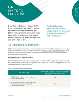
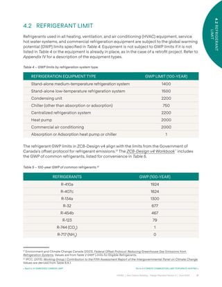
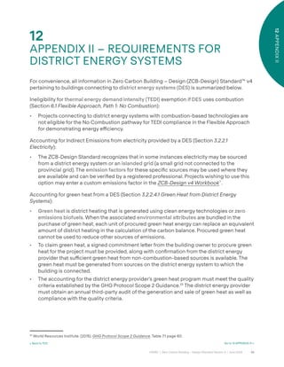

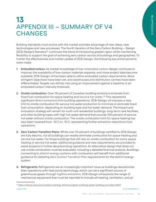
Zero carbon Building Design Guidelines V4
- 2. Copyright © Canada Green Building Council (CAGBC), 2024. These materials may be reproduced in whole or in part without charge or wri˜en permission, provided that appropriate source acknowledgements are made and that no changes are made to the contents. All other rights are reserved. The analyses/views in these materials are those of CAGBC, but these analyses/views do not necessarily re°ect those of CAGBC’s a˛liates including supporters, funders, members, and other participants or any endorsement by CAGBC’s a˛liates. These materials are provided on an “as is” basis, and neither CAGBC nor its a˛liates guarantee any parts or aspects of these materials. CAGBC and its a˛liates are not liable (either directly or indirectly) nor accept any legal responsibility for any issues that may be related to relying on the materials (including any consequences from using/applying the materials’ contents). Each user is solely responsible, at the user’s own risk, for any issues arising from any use or application of the materials’ contents. TRADEMARK Zero Carbon Building® is a registered trademark of the Canada Green Building Council (CAGBC). Zero Carbon Building – Design Standard Version 4 ISBN: 978-1-7781454-8-3
- 3. 3 CAGBC | Zero Carbon Building – Design Standard Version 4 | June 2024 01 INTRODUCTION ............................................................................................................................................................................................8 02 OVERVIEW.................................................................................................................................................................................................... 13 2.1 Project Claims and Marketing..........................................................................................................................................................15 2.2 Eligibility ..................................................................................................................................................................................................15 2.2.1 A˜ached Buildings.................................................................................................................................................................15 2.2.2 Additions.................................................................................................................................................................................. 16 2.3 Emissions Covered ............................................................................................................................................................................ 16 2.4 Required Documentation................................................................................................................................................................ 16 2.5 Requirements at a Glance................................................................................................................................................................17 03 ZERO CARBON BALANCE....................................................................................................................................................................... 21 3.1 Embodied Carbon ...............................................................................................................................................................................22 3.1.1 Whole-Building Life Cycle Assessment........................................................................................................................23 3.2 Operational Carbon...........................................................................................................................................................................25 3.2.1 Direct Emissions ....................................................................................................................................................................25 3.2.1.1 Fugitive Emissions from Refrigerants............................................................................................................25 3.2.1.2 Combustion ............................................................................................................................................................26 3.2.1.2.1 Biogas..................................................................................................................................................27 3.2.1.2.2 Biomass.............................................................................................................................................27 3.2.2 Indirect Emissions................................................................................................................................................................28 3.2.2.1 Electricity...............................................................................................................................................................28 3.2.2.2 Owned Renewable Energy Systems.........................................................................................................29 3.2.2.2.1 Onsite.................................................................................................................................................29 3.2.2.2.2 O˝site................................................................................................................................................ 30 3.2.2.3 Green Power Products ................................................................................................................................... 30 3.2.2.4 District Heating and Cooling.........................................................................................................................31 3.2.2.4.1 Green Heat from District Energy Systems...........................................................................31 3.3 Avoided Emissions.............................................................................................................................................................................32 3.3.1 Exported Green Power........................................................................................................................................................32 3.3.2 Carbon O˝sets ......................................................................................................................................................................33 04 LIMITS TO EMISSIONS............................................................................................................................................................................ 35 4.1 Embodied Carbon Limit....................................................................................................................................................................35 4.2 Refrigerant Limit..................................................................................................................................................................................37 4.3 Onsite Combustion Limit for Space Heating ..........................................................................................................................38 4.4 Onsite Combustion Limit for Service Hot Water...................................................................................................................39 4.5 Limits to Other Sources of Combustion................................................................................................................................... 40 05 ALTERNATIVE DESIGN EVALUATION AND TRANSITION PLAN ................................................................................................41 5.1 Evaluation of Alternative Design Without Onsite Combustion..........................................................................................41 5.2 Zero Carbon Transition Plan...........................................................................................................................................................43 5.3 Financial Analysis ...............................................................................................................................................................................45 5.4 Application to District Energy Systems....................................................................................................................................46 TABLE OF CONTENTS
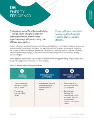
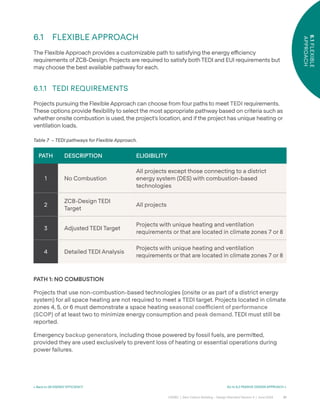
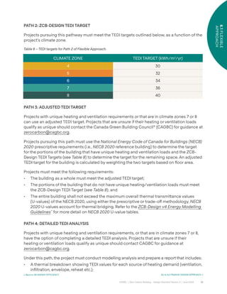
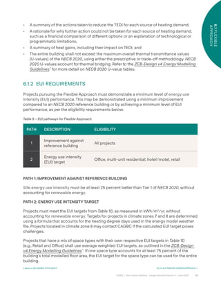
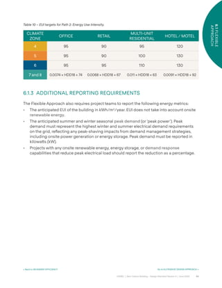
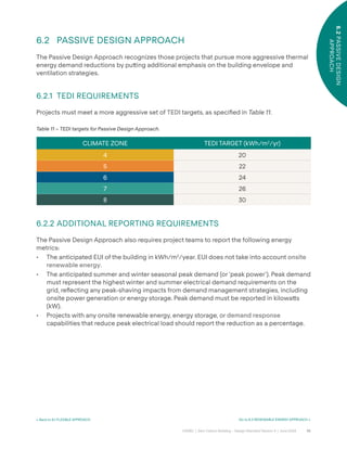
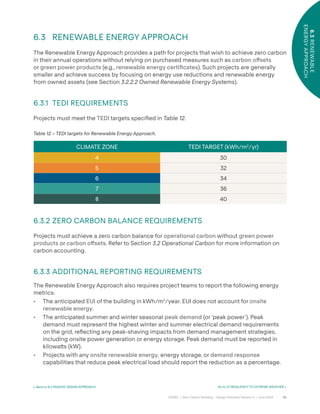
- 4. 4 CAGBC | Zero Carbon Building – Design Standard Version 4 | June 2024 06 ENERGY EFFICIENCY............................................................................................................................................................................... 47 6.1 Flexible Approach.................................................................................................................................................................................51 6.1.1 TEDI Requirements .................................................................................................................................................................51 6.1.2 EUI Requirements..................................................................................................................................................................53 6.1.3 Additional Reporting Requirements..............................................................................................................................54 6.2 Passive Design Approach ...............................................................................................................................................................55 6.2.1 TEDI Requirements...............................................................................................................................................................55 6.2.2 Additional Reporting Requirements.............................................................................................................................55 6.3 Renewable Energy Approach........................................................................................................................................................56 6.3.1 TEDI Requirements ...............................................................................................................................................................56 6.3.2 Zero Carbon Balance Requirements............................................................................................................................56 6.3.3 Additional Reporting Requirements.............................................................................................................................56 07 RESILIENCY TO EXTREME WEATHER................................................................................................................................................. 57 08 AIRTIGHTNESS........................................................................................................................................................................................... 59 09 GRID CITIZENSHIP....................................................................................................................................................................................60 10 IMPACT & INNOVATION........................................................................................................................................................................... 62 11 APPENDIX I – Requirements for Bundled Green Power Products that are not ECOLOGO or Green-e® Certified..64 12 APPENDIX II – Requirements for District Energy Systems..........................................................................................................66 13 APPENDIX III – Summary of v4 Changes........................................................................................................................................... 68 14 APPENDIX IV – Equipment Descriptions........................................................................................................................................... 70 15 GLOSSARY..................................................................................................................................................................................................... 71 16 ACRONYMS.................................................................................................................................................................................................. 76 17 RESOURCES..................................................................................................................................................................................................77 17.1 Embodied Carbon Resources..........................................................................................................................................................77 17.2 Operational Carbon Resources .....................................................................................................................................................78 17.3 Avoided Emissions Resources .......................................................................................................................................................79 17.4 Alternative Design Evaluation and Transition Plan Resources......................................................................................... 80 17.5 Energy E˛ciency Resources .......................................................................................................................................................... 80 17.6 Impact and Innovation Resources.................................................................................................................................................81
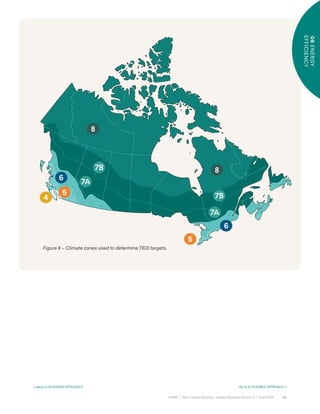
- 5. 5 CAGBC | Zero Carbon Building – Design Standard Version 4 | June 2024 LIST OF FIGURES Figure 1 – Estimated cumulative net global anthropogenic CO2 emissions to limit global warming to 1.5 C...................... 8 Figure 2 – Incremental life cycle returns across Canada........................................................................................................................ 10 Figure 3 – Net present value of deep carbon retroÿts for 1970s vintage buildings....................................................................... 11 Figure 4 – Milestones in the sequence of ZCB-Design and ZCB-Performance. ........................................................................... 14 Figure 5 – Calculating the carbon balance....................................................................................................................................................21 Figure 6 – Embodied carbon life cycle stages............................................................................................................................................23 Figure 7 – Global warming potential (GWP) values of common refrigerants. ...............................................................................26 Figure 8 – Climate zones used to determine TEDI targets..................................................................................................................... 50 LIST OF TABLES Table 1 – Emissions covered by ZCB-Design................................................................................................................................................ 16 Table 2 – ZCB-Design and ZCB-Performance requirements compared.......................................................................................... 20 Table 3 – Embodied carbon intensity targets. .............................................................................................................................................35 Table 4 – GWP limits by refrigeration system type....................................................................................................................................37 Table 5 – 100-year GWP of common refrigerants. .....................................................................................................................................37 Table 6 – The three energy e˛ciency approaches...................................................................................................................................47 Table 7 – TEDI pathways for Flexible Approach..........................................................................................................................................51 Table 8 – TEDI targets for Path 2 of Flexible Approach.............................................................................................................................52 Table 9 – EUI pathways for Flexible Approach. ...........................................................................................................................................53 Table 10 – EUI targets for Path 2: Energy Use Intensity. ...........................................................................................................................54 Table 11 – TEDI targets for Passive Design Approach................................................................................................................................55 Table 12 – TEDI targets for Renewable Energy Approach. ......................................................................................................................56
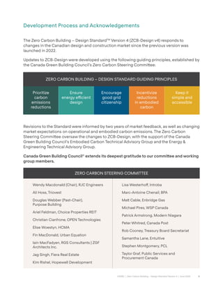
- 6. 6 CAGBC | Zero Carbon Building – Design Standard Version 4 | June 2024 Development Process and Acknowledgements The Zero Carbon Building – Design StandardTM Version 4 (ZCB-Design v4) responds to changes in the Canadian design and construction market since the previous version was launched in 2022. Updates to ZCB-Design were developed using the following guiding principles, established by the Canada Green Building Council’s Zero Carbon Steering Commi˜ee: Revisions to the Standard were informed by two years of market feedback, as well as changing market expectations on operational and embodied carbon emissions. The Zero Carbon Steering Commi˜ee oversaw the changes to ZCB-Design, with the support of the Canada Green Building Council’s Embodied Carbon Technical Advisory Group and the Energy & Engineering Technical Advisory Group. Canada Green Building Council® extends its deepest gratitude to our commi˜ee and working group members. ZERO CARBON BUILDING – DESIGN STANDARD GUIDING PRINCIPLES Prioritize carbon emissions reductions Ensure energy e˛cient design Encourage good grid citizenship Incentivize reductions in embodied carbon Keep it simple and accessible ZERO CARBON STEERING COMMITTEE Wendy Macdonald (Chair), RJC Engineers Ali Hoss, Triovest Douglas Webber (Past-Chair), Purpose Building Ariel Feldman, Choice Properties REIT Christian Cianfrone, OPEN Technologies Elise Woestyn, HCMA Fin MacDonald, Urban Equation Iain MacFadyen, RGS Consultants | ZGF Architects Inc. Jag Singh, Fiera Real Estate Kim Rishel, Hopewell Development Lisa Westerho˝, Introba Marc-Antoine Chenail, BPA Ma˜ Cable, Enbridge Gas Michael Pires, WSP Canada Patrick Armstrong, Modern Niagara Peter Whitred, Canada Post Rob Cooney, Treasury Board Secretariat Samantha Lane, Entuitive Stephen Montgomery, PCL Taylor Graf, Public Services and Procurement Canada
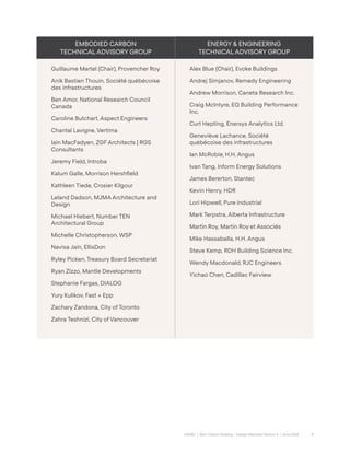
- 7. 7 CAGBC | Zero Carbon Building – Design Standard Version 4 | June 2024 EMBODIED CARBON TECHNICAL ADVISORY GROUP ENERGY & ENGINEERING TECHNICAL ADVISORY GROUP Guillaume Martel (Chair), Provencher Roy Anik Bastien Thouin, Société québécoise des infrastructures Ben Amor, National Research Council Canada Caroline Butchart, Aspect Engineers Chantal Lavigne, Vertima Iain MacFadyen, ZGF Architects | RGS Consultants Jeremy Field, Introba Kalum Galle, Morrison Hershÿeld Kathleen Tiede, Crosier Kilgour Leland Dadson, MJMA Architecture and Design Michael Hiebert, Number TEN Architectural Group Michelle Christopherson, WSP Navisa Jain, EllisDon Ryley Picken, Treasury Board Secretariat Ryan Zizzo, Mantle Developments Stephanie Fargas, DIALOG Yury Kulikov, Fast + Epp Zachary Zandona, City of Toronto Zahra Teshnizi, City of Vancouver Alex Blue (Chair), Evoke Buildings Andrej Simjanov, Remedy Engineering Andrew Morrison, Caneta Research Inc. Craig McIntyre, EQ Building Performance Inc. Curt Hepting, Enersys Analytics Ltd. Geneviève Lachance, Société québécoise des infrastructures Ian McRobie, H.H. Angus Ivan Tang, Inform Energy Solutions James Bererton, Stantec Kevin Henry, HDR Lori Hipwell, Pure Industrial Mark Terpstra, Alberta Infrastructure Martin Roy, Martin Roy et Associés Mike Hassaballa, H.H. Angus Steve Kemp, RDH Building Science Inc. Wendy Macdonald, RJC Engineers Yichao Chen, Cadillac Fairview
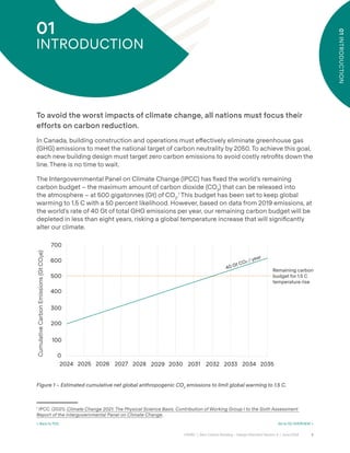
- 8. 8 CAGBC | Zero Carbon Building – Design Standard Version 4 | June 2024 01 INTRODUCTION To avoid the worst impacts of climate change, all nations must focus their efforts on carbon reduction. In Canada, building construction and operations must e˝ectively eliminate greenhouse gas (GHG) emissions to meet the national target of carbon neutrality by 2050. To achieve this goal, each new building design must target zero carbon emissions to avoid costly retroÿts down the line. There is no time to wait. The Intergovernmental Panel on Climate Change (IPCC) has ÿxed the world’s remaining carbon budget – the maximum amount of carbon dioxide (CO2 ) that can be released into the atmosphere – at 500 gigatonnes (Gt) of CO2 .1 This budget has been set to keep global warming to 1.5 C with a 50 percent likelihood. However, based on data from 2019 emissions, at the world’s rate of 40 Gt of total GHG emissions per year, our remaining carbon budget will be depleted in less than eight years, risking a global temperature increase that will signiÿcantly alter our climate. Figure 1 – Estimated cumulative net global anthropogenic CO2 emissions to limit global warming to 1.5 C. 1 IPCC. (2021). Climate Change 2021: The Physical Science Basis. Contribution of Working Group I to the Sixth Assessment Report of the Intergovernmental Panel on Climate Change. 200 100 400 300 500 0 Cumulative Carbon Emissions (Gt CO₂e) 2024 2025 2026 2027 2028 2029 2030 2031 2032 2033 2034 600 700 2035 Remaining carbon budget for 1.5 C temperature rise 40 Gt CO / year 01 INTRODUCTION < Back to TOC Go to 02 OVERVIEW >
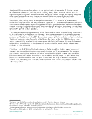
- 9. 9 CAGBC | Zero Carbon Building – Design Standard Version 4 | June 2024 01 INTRODUCTION Staying within the remaining carbon budget and mitigating the e˝ects of climate change requires collective action from across the building sector. Every year that passes without signiÿcantly reducing GHG emissions erodes the global carbon budget, shortening what li˜le time we have leˆ to reach zero carbon and remain within our planetary boundaries.2 Fortunately, the building sector is well-positioned to support Canada’s decarbonization e˝orts. Building operations are responsible for 17 percent of Canada’s carbon emissions,3 with construction and materials representing an estimated 10 percent more.4 The transition to zero- carbon buildings will generate new and innovative design strategies, expanding opportunities for industry growth and job creation. The Canada Green Building Council® (CAGBC) launched the Zero Carbon Building Standards™ (ZCB Standards) in 2017 to assist the industry’s transition to zero carbon. Every day, projects pursuing certiÿcation under the ZCB Standards are pushing the boundaries and demonstrating that there is a zero-carbon future for all buildings. Certifying under the ZCB Standards mean taking responsibility for all carbon emissions over a building’s life cycle. It is an ambitious but nonetheless critical objective, because within the context of a global carbon budget, every kilogram of carbon counts. Published in 2019, CAGBC’s Making the Case for Building to Zero Carbon report conÿrmed that zero-carbon buildings are both technically feasible and ÿnancially viable.5 On average, zero-carbon buildings can provide a positive ÿnancial return over a 25-year life cycle when considering national carbon pollution pricing. They also require only a modest capital cost premium. The ÿnancial returns for zero carbon buildings will only increase as the cost of carbon rises, while they also help mitigate future costs from utilities, regulations, retroÿts and extreme weather. 2 Rockström et al. (2009). Planetary Boundaries: Exploring the Safe Operating Space for Humanity. 3 Environment and Climate Change Canada. (2016). Pan-Canadian Framework on Clean Growth and Climate Change. Canada’s Plan to Address Climate Change and Grow the Economy. 4 Global Alliance for Buildings and Construction. (2024). Global Status Report for Buildings and Construction. 5 Canada Green Building Council. (2019). Making the Case for Building to Zero Carbon. < Back to 01 INTRODUCTION Go to 02 OVERVIEW >
- 10. 10 CAGBC | Zero Carbon Building – Design Standard Version 4 | June 2024 01 INTRODUCTION INCREMENTAL LIFE CYCLE RETURNS ACROSS CANADA CALGARY 1% $32/m2 $18/tCO2 e TORONTO 1% $58/m2 $110/tCO2 e OTTAWA 1% $51/m2 $79/tCO2 e MONTREAL 0% -$4/m2 -$6/tCO2 e HALIFAX 4% $187/m2 $122/tCO2 e VANCOUVER -1% -$55/m2 -$137/tCO2 e Figure 2 – Incremental life cycle returns across Canada.6 In 2021, CAGBC released the Decarbonizing Canada’s Large Buildings report, which studied the costs of deep carbon retroÿts for 1970s and 1990s vintage buildings, identifying key market barriers and solutions. The archetypes within the study can reduce fossil fuel consumption by at least 93 percent, while slashing energy usage by more than 70 percent. Many of the archetypes also yielded a positive ÿnancial return on a deep carbon retroÿt using a 40-year life cycle, with the remainder becoming cost viable as carbon and energy prices increase. 6 Ibid. < Back to 01 INTRODUCTION Go to 02 OVERVIEW >
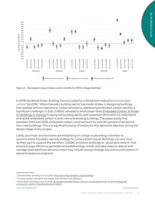
- 11. 11 CAGBC | Zero Carbon Building – Design Standard Version 4 | June 2024 01 INTRODUCTION Figure 3 – Net present value of deep carbon retrofits for 1970s vintage buildings.7 In 2019, the World Green Building Council called for a 40 percent reduction in embodied carbon8 by 2030.9 While Canada’s building sector has made strides in designing buildings that operate without operational carbon emissions, addressing embodied carbon remains a signiÿcant challenge. In 2021, CABGC released a white paper titled Embodied Carbon: A Primer for Buildings in Canada to equip the building sector with essential information to understand and tackle embodied carbon in both new and existing buildings. The paper posits that between 2022 and 2050, embodied carbon could account for over 90 percent of emissions from new buildings. This is a signiÿcant source of emissions that demands a˜ention during the design stage of any project. Lastly, provinces and territories are embarking on a large-scale energy transition to accommodate Canada’s national strategy for a low-carbon future. Buildings can and must do their part to support the transition. CAGBC envisions buildings as “good grid citizens” that ensure energy e˛ciency, generate renewable energy onsite, and take steps to reduce and manage peak electrical demand, which may include energy storage and active participation in demand response programs. 7 Canada Green Building Council (2021). Decarbonizing Canada’s Large Buildings. 8 To assist readers, key terms are bolded and defined in the Glossary. 9 World Green Building Council. (2019). Bringing Embodied Carbon Upfront: Coordinated action for the building and construction sector to tackle embodied carbon. Halifax Montreal Toronto NPV Positive with Positive IRR NPV Negative with Positive IRR NPV Negative with Negative IRR Edmonton Vancouver 1000 900 800 700 600 500 400 300 200 100 0 -100 -200 -300 -400 -500 -600 -700 Low-rise Office Low-rise MURB Mid-rise Office Net Present Value ($/m) Mid-rise MURB Primary School Low-rise Office Low-rise MURB Mid-rise Office Mid-rise MURB Primary School Low-rise Office Low-rise MURB Mid-rise Office Mid-rise MURB Primary School Low-rise Office Low-rise MURB Mid-rise Office Mid-rise MURB Primary School Low-rise Office Low-rise MURB Mid-rise Office Mid-rise MURB Primary School < Back to 01 INTRODUCTION Go to 02 OVERVIEW >
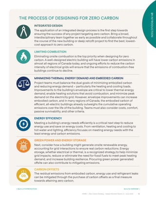
- 12. 12 CAGBC | Zero Carbon Building – Design Standard Version 4 | June 2024 01 INTRODUCTION THE PROCESS OF DESIGNING FOR ZERO CARBON INTEGRATED DESIGN The application of an integrated design process is the ÿrst step towards ensuring the success of any project targeting zero carbon. Bring a broad, interdisciplinary team together as early as possible and collaborate throughout the course of the new building or deep retroÿt project to ÿnd the best, lowest- cost approach to zero carbon. LIMITING COMBUSTION Eliminating onsite combustion is the top priority when designing for zero carbon. A well-designed electric building will have lower carbon emissions in almost all regions of Canada today, and ongoing e˝orts to reduce the carbon intensity of electrical grids will ensure that the emissions of combustion-free buildings continue to decline. MINIMIZING THERMAL ENERGY DEMAND AND EMBODIED CARBON Project teams must balance the dual goals of minimizing embodied carbon and reducing energy demand – particularly the heating and cooling loads. Improvements to the building’s envelope are critical to lower thermal energy demand, enable heating solutions that avoid combustion, and minimize peak demand on the electricity grid. However, envelope improvements can increase embodied carbon, and in many regions of Canada, the embodied carbon of e˛cient, all-electric buildings already outweighs the cumulative operating emissions over the life of the building. Teams must also consider costs, comfort, passive survivability, and other criteria. ENERGY EFFICIENCY Meeting a building’s energy needs e˛ciently is a critical next step to reduce energy use and save on energy costs. From ventilation, heating and cooling to hot water and lighting, e˛ciency focuses on meeting energy needs with the least energy and carbon emissions. GREEN POWER AND ENERGY STORAGE Next, consider how a building might generate onsite renewable energy, accounting for grid interactions to ensure real carbon reductions. Energy storage, whether electrical or thermal, is a recognized strategy to help minimize grid impacts, reduce or eliminate the need for fossil fuels to meet peak heating demand, and increase building resilience. Procuring green power generated o˝site can also contribute to mitigating emissions. CARBON OFFSETS The residual emissions from embodied carbon, energy use and refrigerant leaks can be mitigated through the purchase of carbon o˝sets as a ÿnal measure towards a˜aining zero carbon. 01 INTRODUCTION < Back to 01 INTRODUCTION Go to 02 OVERVIEW >
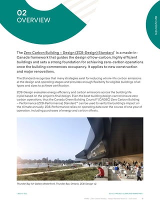
- 13. 13 CAGBC | Zero Carbon Building – Design Standard Version 4 | June 2024 02 OVERVIEW The Zero Carbon Building – Design (ZCB-Design) Standard™ is a made-in- Canada framework that guides the design of low-carbon, highly efficient buildings and sets a strong foundation for achieving zero-carbon operations once the building commences occupancy. It applies to new construction and major renovations. The Standard recognizes that many strategies exist for reducing whole-life carbon emissions at the design and operating stages and provides enough °exibility for eligible buildings of all types and sizes to achieve certiÿcation. ZCB-Design evaluates energy e˛ciency and carbon emissions across the building life cycle based on the project’s ÿnal design. Even the best building design cannot ensure zero carbon operations, thus the Canada Green Building Council® (CAGBC) Zero Carbon Building – Performance (ZCB-Performance) Standard™ can be used to verify the building’s impact on the climate annually. ZCB-Performance relies on operating data over the course of one year of operation, including purchases of energy and carbon o°sets. 02 OVERVIEW < Back to TOC Go to 2.1 PROJECT CLAIMS AND MARKETING > Thunder Bay Art Gallery Waterfront, Thunder Bay, Ontario, ZCB-Design v2.
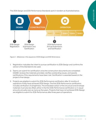
- 14. 14 CAGBC | Zero Carbon Building – Design Standard Version 4 | June 2024 02 OVERVIEW Figure 4 – Milestones in the sequence of ZCB-Design and ZCB-Performance. DESIGN 1 ZCB-Design Registration CONSTRUCTION 2 ZCB-Design Submission and Certiÿcation OPERATION 3 ZCB-Performance Annual Submission and Certiÿcation The ZCB-Design and ZCB-Performance Standards work in tandem as illustrated below. YEAR 1 YEAR 2 YEAR 3 YEAR 4 YEAR 5 1. Registration indicates the intent to pursue certiÿcation to ZCB-Design and conÿrms the version of the Standard to be used. 2. Teams can submit for certiÿcation once the construction documents are completed. CAGBC reviews the materials provided, clariÿes outstanding issues, and awards certiÿcations if the requirements have been met. Certiÿcation is awarded based on the project’s ÿnal design. 3. Projects are eligible to submit for ZCB-Performance certiÿcation aˆer 12 months of operations if they have achieved ZCB-Design. The ÿrst ZCB-Performance certiÿcation includes veriÿcation of airtightness. The embodied carbon of the structural and envelope materials must also be o˝set, either in the ÿrst ZCB-Performance certiÿcation or in equal amounts annually over as many as ÿve years. Projects that have not achieved ZCB-Design are eligible to submit for ZCB-Performance aˆer three years of operations. < Back to 02 OVERVIEW Go to 2.1 PROJECT CLAIMS AND MARKETING >
- 15. 15 CAGBC | Zero Carbon Building – Design Standard Version 4 | June 2024 2.1 PROJECT CLAIMS AND MARKETING 2.1 PROJECT CLAIMS AND MARKETING ZCB-Design certiÿed projects are not permi˜ed to display a certiÿcation mark (logo and year) on the building or make a claim of zero carbon operations. Communications about the achievement of ZCB-Design certiÿcation should instead re°ect the expectation that operations will be veriÿed through certiÿcation under the ZCB-Performance Standard following building occupancy. More information on how to market ZCB-Design certiÿed projects can be found on cagbc.org. ZCB-Design certiÿcation may not be used to make a carbon-neutral claim about a product or service originating from a ZCB-Design certiÿed building; however, it may form part of a strategy to achieve a carbon neutral claim. 2.2 ELIGIBILITY The ZCB-Design Standard applies to new buildings and major renovations to existing buildings, provided they include HVAC, envelope, and/or interior renovations that require a new certiÿcate of occupancy and/or prevent normal building operations from occurring while they are in process. Proposed changes of use to the building are also considered major renovations. ZCB-Design applies to all buildings except single and multi-family residential buildings that fall under Part 9 of the National Building Code. That is, the Standard applies to all buildings except residential buildings that are three storeys or less, and smaller than 600 m2 . ZCB-Design was created to evaluate entire individual buildings but may also be applied to a˜ached buildings and additions, per Sections 2.2.1 and 2.2.2. Multiple buildings that share a common site cannot be certiÿed under a single project unless a˜ached by programmable space. Buildings that have no physical connection or are connected only by corridors, parking, mechanical rooms, or storage rooms are considered separate buildings. 2.2.1 ATTACHED BUILDINGS A building that is a˜ached to another building may independently pursue ZCB-Design certiÿcation. The following rules apply: 1. An a˜ached building must be physically distinct to be considered separately for certiÿcation. 2. The a˜ached building must have a distinct identity. This ensures that the certiÿcation is communicated appropriately to the building users and the public. 3. A˜ached buildings generally share a common site and will need to consider appropriate separation of that site to determine the emission sources to include in the project. 4. An a˜ached building must have a separate ventilation system and energy meters capable of measuring energy use for electricity, heating, and cooling. This is necessary to demonstrate compliance with the energy and carbon requirements of the Standard. 5. Applicants must seek clariÿcation with CAGBC by emailing zerocarbon@cagbc.org if they are uncertain about a˜ached building compliance. < Back to 02 OVERVIEW Go to 2.3 EMISSIONS COVERED >
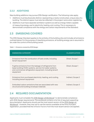
- 16. 16 CAGBC | Zero Carbon Building – Design Standard Version 4 | June 2024 2.3 EMISSIONS COVERED 2.2.2 ADDITIONS New building additions may pursue ZCB-Design certiÿcation. The following rules apply: 1. Additions must be physically distinct, representing a newly constructed, unique area of a building. The distinct space must also be re°ected in the project name when registering. 2. Additions must have separate ventilation systems as well as energy meters capable of measuring energy use for electricity, heating, and cooling. This is necessary to demonstrate compliance with the energy and carbon requirements of the Standard. 2.3 EMISSIONS COVERED The ZCB-Design Standard applies to the entirety of the building site and includes all emissions outlined below. For the purpose of classifying emissions, all building energy use is assumed to be under the control of the building owner. 2.4 REQUIRED DOCUMENTATION Applicants must complete the ZCB-Design v4 Workbook™ to demonstrate compliance with ZCB-Design requirements. The workbook contains a full list of required supporting documentation. Applicants should use the most recent version of the ZCB-Design v4 Workbook™ ; however, they may opt to use the version available at the time of project registration, provided that the emission factors from the most recent version are applied. EMISSIONS CATEGORY CLASSIFICATION Emissions from the combustion of fuels onsite, including tenant equipment Direct, Scope 1 Fugitive emissions from the leakage of refrigerants from base building HVAC systems, service hot water systems, and commercial refrigeration equipment, including tenant equipment Direct, Scope 1 Emissions from purchased electricity, heating, and cooling, including tenant equipment Indirect, Scope 2 Embodied carbon emissions that are associated with new structural and building envelope materials Indirect, Scope 3 Table 1 – Emissions covered by ZCB-Design. < Back to 2.1 PROJECT CLAIMS AND MARKETING Go to 2.5 REQUIREMENTS AT A GLANCE >
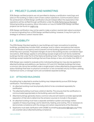
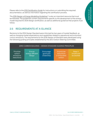
- 17. 17 CAGBC | Zero Carbon Building – Design Standard Version 4 | June 2024 2.5 REQUIREMENTS AT A GLANCE Please refer to the ZCB Certification Guide for instructions on submi˜ing the required documentation, as well as information regarding the certiÿcation process. The ZCB-Design v4 Energy Modelling Guidelines™ is also an important resource that must be followed. The guidelines contain requirements speciÿc to the development of the energy model required for ZCB-Design certiÿcation, as well as additional guidance that projects must follow. 2.5 REQUIREMENTS AT A GLANCE Revisions to the ZCB-Design Standard were informed by two years of market feedback, as well as changing market expectations and capabilities related to operational and embodied carbon emissions. The requirements for the ZCB-Design v4 Standard were developed using the following guiding principles established by the Zero Carbon Steering Commi˜ee: ZERO CARBON BUILDING – DESIGN STANDARD GUIDING PRINCIPLES Prioritize carbon emissions reductions Ensure energy e˛cient design Encourage good grid citizenship Incentivize reductions in embodied carbon Keep it simple and accessible < Back to 2.1 PROJECT CLAIMS AND MARKETING Go to 03 ZERO CARBON BALANCE >
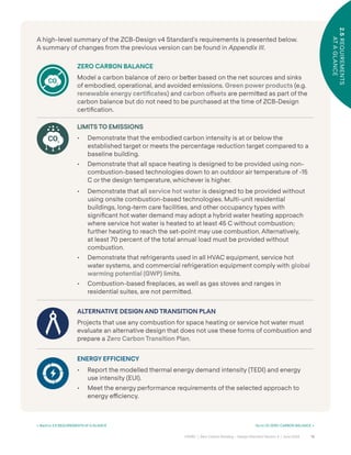
- 18. 18 CAGBC | Zero Carbon Building – Design Standard Version 4 | June 2024 2.5 REQUIREMENTS AT A GLANCE A high-level summary of the ZCB-Design v4 Standard’s requirements is presented below. A summary of changes from the previous version can be found in Appendix III. ZERO CARBON BALANCE Model a carbon balance of zero or be˜er based on the net sources and sinks of embodied, operational, and avoided emissions. Green power products (e.g. renewable energy certiÿcates) and carbon o°sets are permi˜ed as part of the carbon balance but do not need to be purchased at the time of ZCB-Design certiÿcation. LIMITS TO EMISSIONS • Demonstrate that the embodied carbon intensity is at or below the established target or meets the percentage reduction target compared to a baseline building. • Demonstrate that all space heating is designed to be provided using non- combustion-based technologies down to an outdoor air temperature of -15 C or the design temperature, whichever is higher. • Demonstrate that all service hot water is designed to be provided without using onsite combustion-based technologies. Multi-unit residential buildings, long-term care facilities, and other occupancy types with signiÿcant hot water demand may adopt a hybrid water heating approach where service hot water is heated to at least 45 C without combustion; further heating to reach the set-point may use combustion. Alternatively, at least 70 percent of the total annual load must be provided without combustion. • Demonstrate that refrigerants used in all HVAC equipment, service hot water systems, and commercial refrigeration equipment comply with global warming potential (GWP) limits. • Combustion-based ÿreplaces, as well as gas stoves and ranges in residential suites, are not permi˜ed. ALTERNATIVE DESIGN AND TRANSITION PLAN Projects that use any combustion for space heating or service hot water must evaluate an alternative design that does not use these forms of combustion and prepare a Zero Carbon Transition Plan. ENERGY EFFICIENCY • Report the modelled thermal energy demand intensity (TEDI) and energy use intensity (EUI). • Meet the energy performance requirements of the selected approach to energy e˛ciency. 2.5 REQUIREMENTS AT A GLANCE < Back to 2.5 REQUIREMENTS AT A GLANCE Go to 03 ZERO CARBON BALANCE >
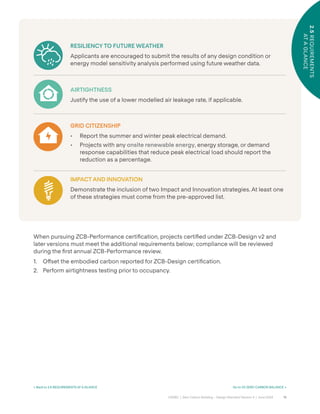
- 19. 19 CAGBC | Zero Carbon Building – Design Standard Version 4 | June 2024 2.5 REQUIREMENTS AT A GLANCE When pursuing ZCB-Performance certiÿcation, projects certiÿed under ZCB-Design v2 and later versions must meet the additional requirements below; compliance will be reviewed during the ÿrst annual ZCB-Performance review. 1. O˝set the embodied carbon reported for ZCB-Design certiÿcation. 2. Perform airtightness testing prior to occupancy. RESILIENCY TO FUTURE WEATHER Applicants are encouraged to submit the results of any design condition or energy model sensitivity analysis performed using future weather data. AIRTIGHTNESS Justify the use of a lower modelled air leakage rate, if applicable. GRID CITIZENSHIP • Report the summer and winter peak electrical demand. • Projects with any onsite renewable energy, energy storage, or demand response capabilities that reduce peak electrical load should report the reduction as a percentage. IMPACT AND INNOVATION Demonstrate the inclusion of two Impact and Innovation strategies. At least one of these strategies must come from the pre-approved list. 2.5 REQUIREMENTS AT A GLANCE < Back to 2.5 REQUIREMENTS AT A GLANCE Go to 03 ZERO CARBON BALANCE >
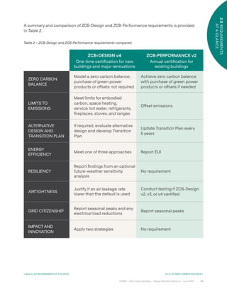
- 20. 20 CAGBC | Zero Carbon Building – Design Standard Version 4 | June 2024 2.5 REQUIREMENTS AT A GLANCE ZCB-DESIGN v4 One-time certiÿcation for new buildings and major renovations ZCB-PERFORMANCE v2 Annual certiÿcation for existing buildings ZERO CARBON BALANCE Model a zero carbon balance; purchase of green power products or o˝sets not required Achieve zero carbon balance with purchase of green power products or o˝sets if needed LIMITS TO EMISSIONS Meet limits for embodied carbon, space heating, service hot water, refrigerants, ÿreplaces, stoves, and ranges O˝set emissions ALTERNATIVE DESIGN AND TRANSITION PLAN If required, evaluate alternative design and develop Transition Plan Update Transition Plan every 5 years ENERGY EFFICIENCY Meet one of three approaches Report EUI RESILIENCY Report ÿndings from an optional future-weather sensitivity analysis No requirement AIRTIGHTNESS Justify if an air leakage rate lower than the default is used Conduct testing if ZCB-Design v2, v3, or v4 certiÿed GRID CITIZENSHIP Report seasonal peaks and any electrical load reductions Report seasonal peaks IMPACT AND INNOVATION Apply two strategies No requirement Table 2 – ZCB-Design and ZCB-Performance requirements compared. A summary and comparison of ZCB-Design and ZCB-Performance requirements is provided in Table 2. < Back to 2.5 REQUIREMENTS AT A GLANCE Go to 03 ZERO CARBON BALANCE >
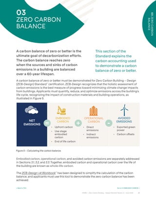
- 21. 21 CAGBC | Zero Carbon Building – Design Standard Version 4 | June 2024 03 ZERO CARBON BALANCE < Back to TOC Go to 3.1 EMBODIED CARBON > 03 ZERO CARBON BALANCE This section of the Standard explains the carbon accounting used to demonstrate a carbon balance of zero or be˜er. A carbon balance of zero or better is the ultimate goal of decarbonization efforts. The carbon balance reaches zero when the sources and sinks of carbon emissions in a building are balanced over a 60-year lifespan. A carbon balance of zero or be˜er must be demonstrated for Zero Carbon Building – Design (ZCB-Design) Standard™ certiÿcation. ZCB-Design recognizes that the holistic assessment of carbon emissions is the best measure of progress toward minimizing climate change impacts from buildings. Applicants must quantify, reduce, and optimize emissions across the building’s life cycle, recognizing the impact of construction materials and building operations, as illustrated in Figure 5. Embodied carbon, operational carbon, and avoided carbon emissions are separately addressed in Sections 3.1, 3.2, and 3.3. Together, embodied carbon and operational carbon over the life of the building are known as whole-life carbon. The ZCB-Design v4 Workbook™ has been designed to simplify the calculation of the carbon balance, and applicants must use this tool to demonstrate the zero carbon balance has been achieved. OPERATIONAL CARBON • Direct emissions • Indirect emissions EMBODIED CARBON • Upfront carbon • Use stage embodied carbon • End of life carbon + - AVOIDED EMISSIONS • Exported green power • Carbon o˝sets = NET EMISSIONS Figure 5 – Calculating the carbon balance.
- 22. 22 CAGBC | Zero Carbon Building – Design Standard Version 4 | June 2024 3.1 EMBODIED CARBON < Back to 03 ZERO CARBON BALANCE Go to 3.2 OPERATIONAL CARBON > 3.1 EMBODIED CARBON Embodied carbon emissions are derived from the manufacturing, transport, installation, use, and end-of-life of building materials. In many regions of Canada, an e˛cient, all- electric building’s embodied carbon will outweigh its cumulative operating emissions over its entire lifespan.10 Globally, embodied carbon emissions represent approximately 10 percent of all energy-related carbon emissions.11 Furthermore, emissions occurring during the production and construction phases of a building, a subset of embodied carbon referred to as upfront carbon, are released into the atmosphere before the building is even operational; given that the timeframe for meaningful climate action is shrinking, there is a growing awareness of the critical importance of addressing this upfront carbon. The ZCB-Design Standard focuses on carbon emissions across the entire life cycle of the building. As such, reductions in embodied carbon should be pursued as part of an approach that includes consideration of carbon from building operations (‘operational carbon’). Decisions about embodied carbon may impact operational carbon and vice versa. To assess embodied carbon’s contribution to the carbon balance of the project, a whole- building life cycle assessment (wbLCA) must be done in conformity with Section 3.1.1 Whole- Building Life Cycle Assessment. Projects must also report their embodied carbon intensity or the total embodied carbon divided by the built °oor area. It should be noted that built ˝oor area includes the °oor area of underground spaces including parking but excludes balconies and terraces.12 10 Derived from: Canada Green Building Council. (2021). Embodied Carbon: A Primer for Buildings in Canada. 11 Global Alliance for Buildings and Construction. (2024). Global Status Report for Buildings and Construction, p. 29. This figure may be conservative as it only includes concrete, steel, aluminum, brick, and glass. It also only accounts for manufacturing and does not include other life cycle stages (construction, use, and end of life). 12 For guidance on calculation of embodied carbon intensity see the National Research Council’s 2024 National Whole-building Life Cycle Assessment Practitioner’s Guide: Guidance for Compliance Reporting of Embodied Carbon in Canadian Building Construction. Embodied carbon can signiÿcantly outweigh operational carbon, and most of it is emi˜ed before a building is even operational.
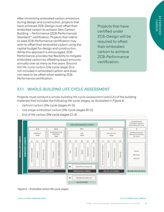
- 23. 23 CAGBC | Zero Carbon Building – Design Standard Version 4 | June 2024 3.1 EMBODIED CARBON < Back to 03 ZERO CARBON BALANCE Go to 3.2 OPERATIONAL CARBON > Projects that have certiÿed under ZCB-Design will be required to o˝set their embodied carbon to achieve ZCB-Performance certiÿcation. Aˆer minimizing embodied carbon emissions during design and construction, projects that have achieved ZCB-Design must o˝set their embodied carbon to achieve Zero Carbon Building – Performance (ZCB-Performance) Standard™ certiÿcation. Projects that intend to seek ZCB-Performance certiÿcation may wish to o˝set their embodied carbon using the capital budget for design and construction. While this approach is encouraged, ZCB- Performance provides the °exibility to mitigate embodied carbon by o˝se˜ing equal amounts annually over as many as ÿve years. Beyond the life cycle carbon (life cycle stage D) is not included in embodied carbon and does not need to be o˝set when seeking ZCB- Performance certiÿcation. 3.1.1 WHOLE-BUILDING LIFE CYCLE ASSESSMENT Projects must conduct a whole-building life cycle assessment (wbLCA) of the building materials that includes the following life cycle stages, as illustrated in Figure 6: • Upfront carbon (life cycle stages A1-5) • Use stage embodied carbon (life cycle stages B1-5) • End of life carbon (life cycle stages C1-4) Figure 6 – Embodied carbon life cycle stages. WHOLE-LIFE CARBON EMBODIED CARBON UPFRONT CARBON OPERATIONAL CARBON OUT OF SCOPE BEYOND THE LIFE CYCLE USE STAGE EMBODIED CARBON END OF LIFE CARBON Raw material supply Transport Manufacturing PRODUCT stage A1-3 A1 A2 A3 Construction-installation process Transport CONSTRUCTION PROCESS stage A4 A5 A4-5 Operational energy use B6 Operational water use B7 B1 B2 B3 B4 B5 Use Maintenance Repair Replacement Refurbishment B1-7 USE stage Transport Waste processing Disposal De-construction / Demolition C1 C2 C3 C4 C1-4 END OF LIFE stage D Beneÿts and loads beyond the building life cycle Supplementary information beyond the building life cycle Reuse Recovery Recycle
- 24. 24 CAGBC | Zero Carbon Building – Design Standard Version 4 | June 2024 3.1 EMBODIED CARBON < Back to 03 ZERO CARBON BALANCE Go to 3.2 OPERATIONAL CARBON > The wbLCA must be conducted using the methodology from the National Research Council (NRC) – National Whole-Building Life Cycle Assessment Practitioner’s Guide: Guidance for Compliance Reporting of Embodied Carbon in Canadian Building Construction (hereaˆer referred to as the National wbLCA Practitioner’s Guide). This document provides practical guidance on how to assess and demonstrate reductions in the estimated embodied carbon of new construction and renovation designs. It is meant to complement and be used in conjunction with the National Guidelines for Whole-Building Life Cycle Assessment. The National wbLCA Practitioner’s Guide was created to enable greater consistency in the methodologies, boundaries, and assumptions used in wbLCAs for Part 3 buildings that intend to demonstrate compliance with certiÿcation programs and jurisdictional requirements. Using a common Canadian methodology, it streamlines the work for practitioners and begins to allow for program comparisons. Projects must adhere to the following direction when applying the National wbLCA Practitioner’s Guide. Where there are di˝erences between the guide and the ZCB-Design Standard, the la˜er takes precedence. Projects must: 1. Follow the Cradle-to-Grave Embodied Carbon Assessments approach outlined in the guide, addressing life cycle stages A1-A5, B1-5, and C1-C4. The guide provides direction on handling stages for which information is not available. As noted in the guide, life cycle stage D shall not be included in the embodied carbon calculations used for compliance but may be calculated and reported separately. 2. Follow the required scope elements for structure and enclosure, speciÿcally substructure (foundations, subgrade enclosures, slab-on-grades) and shell (superstructure, exterior vertical enclosures, exterior horizontal enclosures). Currently, ZCB-Design v4 does not include those elements identiÿed as ‘optional scope’ (e.g., interiors, sitework, and mechanical, electrical, and plumbing systems) in assessing embodied carbon’s contribution to the project’s carbon balance. 3. Conduct a wbLCA for each building. Where buildings a˜ach through an underground parking garage, each building must pursue certiÿcation independently, as noted in Section 2.2 Eligibility. Project teams must separate the embodied carbon assessment for the underground space and appropriately a˜ribute it to the buildings aboveground based on their °oor areas or another suitable methodology. While the National wbLCA Practitioner’s Guide allows for wbLCA assessments to be completed on multiple buildings joined only by underground parking, ZCB-Design v4 does not. The embodied carbon assessment must re°ect the Construction Documents Stage, as noted in the National wbLCA Practitioner’s Guide; an Early Design Stage assessment cannot be used for certiÿcation. Note, it is recommended that discussions on embodied carbon begin during pre-design, and that analysis begin no later than schematic design to in°uence project outcomes.
- 25. 25 CAGBC | Zero Carbon Building – Design Standard Version 4 | June 2024 3.2 OPERATIONAL CARBON < Back to 3.1 EMBODIED CARBON Go to 3.3 AVOIDED EMISSIONS > 3.2 OPERATIONAL CARBON Operational carbon emissions are associated with energy use and potential releases of refrigerants during regular building operations. When targeting ZCB-Design certiÿcation, reducing fossil fuel consumption and the resulting operational carbon, is the priority. Once occupied, operational carbon becomes the critical measure of annual carbon emissions. To achieve ZCB-Performance certiÿcation, operational carbon must be compensated for with avoided emissions (carbon o°sets and exported green power) to demonstrate that a building has minimized its climatic impact during the performance period. Operational carbon must be assessed and reported in the ZCB-Design v4 Workbook™ , following the details below. While this section details how projects account for operational carbon in the carbon balance, Section 4.0 Limits to Emissions speciÿes the maximum limits for several sources of operational carbon. 3.2.1 DIRECT EMISSIONS Direct emissions refer to emissions that occur at the project site because of the combustion of fuels or the release of refrigerants. 3.2.1.1 FUGITIVE EMISSIONS FROM REFRIGERANTS Low-carbon designs oˆen take advantage of e˛cient heat pump technology. Refrigerants used in heat pump equipment can contribute to climate change if they leak into the atmosphere or are improperly disposed of. Project teams should consider the global warming potential (GWP) of refrigerant options when making design decisions, as the heat-trapping potential of some can be hundreds or even thousands of times greater than other choices. ZCB-Design certiÿcation requires projects to report the total quantity, type, and GWP of each refrigerant contained in all base building HVAC systems, service hot water systems, and commercial refrigeration equipment. The total global warming impact of the refrigerants will be assessed in the ZCB-Design v4 Workbook™ , enabling project teams to understand how refrigerants impact the carbon balance. The Workbook includes GWP values for common refrigerants, referencing the IPCC 5th Assessment Report as shown in Table 5 of Section 4.2 Refrigerant Limit. In calculating the carbon balance, the ZCB-Design v4 Workbook™ also incorporates assumptions for annual average refrigerant leakage. The ZCB-Performance Standard requires that any fugitive refrigerant emissions be o˝set. The ZCB-Design Standard leverages the GHG Protocol’s Corporate Accounting and Reporting Standard methodology for quantifying emissions from building operations.
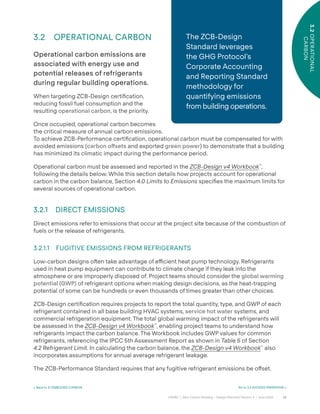
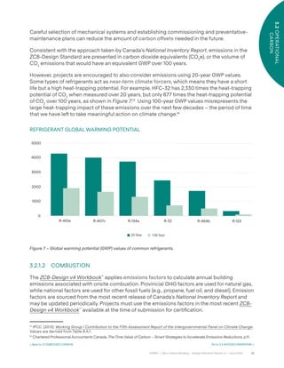
- 26. 26 CAGBC | Zero Carbon Building – Design Standard Version 4 | June 2024 3.2 OPERATIONAL CARBON < Back to 3.1 EMBODIED CARBON Go to 3.3 AVOIDED EMISSIONS > Careful selection of mechanical systems and establishing commissioning and preventative- maintenance plans can reduce the amount of carbon o°sets needed in the future. Consistent with the approach taken by Canada’s National Inventory Report, emissions in the ZCB-Design Standard are presented in carbon dioxide equivalents (CO2 e), or the volume of CO2 emissions that would have an equivalent GWP over 100 years. However, projects are encouraged to also consider emissions using 20-year GWP values. Some types of refrigerants act as near-term climate forcers, which means they have a short life but a high heat-trapping potential. For example, HFC-32 has 2,330 times the heat-trapping potential of CO2 when measured over 20 years, but only 677 times the heat-trapping potential of CO2 over 100 years, as shown in Figure 7.13 Using 100-year GWP values misrepresents the large heat-trapping impact of these emissions over the next few decades – the period of time that we have leˆ to take meaningful action on climate change.14 REFRIGERANT GLOBAL WARMING POTENTIAL 3.2.1.2 COMBUSTION The ZCB-Design v4 Workbook™ applies emissions factors to calculate annual building emissions associated with onsite combustion. Provincial GHG factors are used for natural gas, while national factors are used for other fossil fuels (e.g., propane, fuel oil, and diesel). Emission factors are sourced from the most recent release of Canada’s National Inventory Report and may be updated periodically. Projects must use the emissions factors in the most recent ZCB- Design v4 Workbook™ available at the time of submission for certiÿcation. 13 IPCC. (2013). Working Group I Contribution to the Fifth Assessment Report of the Intergovernmental Panel on Climate Change. Values are derived from Table 8.A.1. 14 Chartered Professional Accountants Canada, The Time Value of Carbon – Smart Strategies to Accelerate Emissions Reductions, p.11. Figure 7 – Global warming potential (GWP) values of common refrigerants. R-410a 20 Year 100 Year 5000 4000 3000 2000 1000 0 R-407c R-134a R-32 R-454b R-123
- 27. 27 CAGBC | Zero Carbon Building – Design Standard Version 4 | June 2024 3.2 OPERATIONAL CARBON < Back to 3.1 EMBODIED CARBON Go to 3.3 AVOIDED EMISSIONS > Fuel used in emergency backup generators does not need to be estimated for ZCB-Design certiÿcation; however, it must be included in the carbon balance for ZCB-Performance certiÿcation. 3.2.1.2.1 BIOGAS The ZCB-Design Standard recognizes the beneÿts of certain forms of renewable natural gas (biogas). Eligible biogas resources that can be used onsite include gaseous products produced by the anaerobic decomposition of organic wastes from one of the following sources: 1. Sewage treatment plants; 2. Manure and other farm and food/feed-based anaerobic digestion processing facilities; or 3. Landÿll gas. Applicants must either produce their own biogas onsite, or purchase biogas from their natural gas provider for it to be eligible. Eligible biogas is treated as a zero emissions biofuel and assigned an emissions factor of zero; it does not contribute to direct emissions. ZCB-Design certiÿcation does not require a contract for the purchase of biogas; purchases are veriÿed as part of ZCB-Performance certiÿcation. However, projects must show proof that an eligible supply is available, as noted in the ZCB-Design v4 Workbook™ . 3.2.1.2.2 BIOMASS The ZCB-Design Standard does not treat all biomass as carbon neutral but does recognize the beneÿts of certain forms of renewable biomass. As such, applicants who use an onsite form of biomass may propose more speciÿc emissions factors where they can be veriÿed by a registered professional. Biomass resources used onsite that are eligible to be treated as zero emissions biofuels15 include: 1. Solid biomass removed from ÿelds and forests that are managed by following sound environmental management practices.16 Solid biomass can either be whole plants, parts of plants, or harvesting and industrial by-product residues arising from the harvesting and processing of agricultural crops or forestry products that would otherwise be landÿlled or incinerated; 2. Dedicated energy crops with a rotation of less than 10 years; and 3. Liquid fuels derived from biomass as deÿned in items (1) and (2) above, including, among other things, ethanol, biodiesel, and methanol. 15 ‘Zero emissions’ is meant to characterize certain biofuels from a net-carbon emissions perspective; it is understood that other combustion products are released during combustion. 16 Refer to UL 2854 Standard for Sustainability for Renewable Low-Impact Electricity Products for a definition of ‘sound environmental management practices’.
- 28. 28 CAGBC | Zero Carbon Building – Design Standard Version 4 | June 2024 3.2 OPERATIONAL CARBON Biomass resources that are ineligible to be treated as zero emissions biofuels include: 1. Municipal solid waste; and 2. Those manufacturing process by-products that have been treated in the manners listed below: i. Wood coated with paint, plastics or Formica; ii. Wood treated with preservatives containing halogens, chlorine or halide like chromated copper arsenate or arsenic; iii. Wood that has been treated with adhesives; and iv. Railroad ties. If the treated biomass types (per (2) above) comprise one percent or less by weight of the total biomass used, and the remainder is from eligible sources of biomass, all biomass may be treated as a zero emissions biofuel. Zero emissions biofuels are assigned an emissions factor of zero and do not contribute to direct emissions. ZCB-Design certiÿcation does not require a contract for the purchase of biomass; purchases are veriÿed as part of ZCB-Performance certiÿcation. However, projects must show proof that an eligible supply is available, as noted in the ZCB-Design v4 Workbook™ . 3.2.2 INDIRECT EMISSIONS Indirect emissions refer to emissions that do not occur directly within the project site, such as those emissions associated with purchased energy, water use, waste, and transportation from commuting. As detailed below, indirect emissions within the scope of ZCB-Design certiÿcation include only the emissions associated with purchased energy, such as electricity or thermal energy. 3.2.2.1 ELECTRICITY Provincial location-based electricity grid emissions factors are used to represent the average emissions of all grid-connected electricity generation in a province. Provincial location- based electricity grid emissions factors are included in the ZCB-Design v4 Workbook™ , which is periodically updated to re°ect the latest emission factors from Environment and Climate Change Canada’s National Inventory Report.17 Projects may substitute a market-based residual mix emissions factor if their local utility has published one. Residual mix emissions factors are an emerging way to account for the retirement of green power products within a speciÿc geographic boundary; however, they are not widely available in North America. Projects wishing to use this option may enter a custom emissions factor in the ZCB-Design v4 Workbook™ and provide the source of the residual mix emissions factor. 17 For the latest version of the report, go to Environment and Climate Change Canada’s National Inventory Report webpage and find the most recent Inventory Report. In past years, electricity emission factors have been in Part 3, Annex 13. Alternatively, see “C-Tables-Electricity-Canada-Provinces-Territories” on Canada’s Official Greenhouse Gas Inventory page. < Back to 3.1 EMBODIED CARBON Go to 3.3 AVOIDED EMISSIONS >
- 29. 29 CAGBC | Zero Carbon Building – Design Standard Version 4 | June 2024 3.2 OPERATIONAL CARBON The ZCB-Design Standard recognizes that electricity may be sourced from a district energy system or an islanded grid (a small grid not connected to the provincial grid). The emission factors for these speciÿc sources may be used where they are available and can be veriÿed by a registered professional. Projects wishing to use this option may enter a custom emissions factor in the ZCB-Design v4 Workbook™ . Electricity used by electric vehicle charging stations that service vehicles used outside the project site, regardless of whether the vehicles are °eet vehicles or otherwise, should be separately metered and excluded from the calculation of indirect emissions from grid electricity. 3.2.2.2 OWNED RENEWABLE ENERGY SYSTEMS Owned renewable energy systems, whether onsite or o˝site, reduce the need for grid electricity, fuel, heating and/or cooling, lowering the emissions associated with these energy sources. Renewable energy systems typically take the form of solar or wind power generation and solar thermal heating. If more green power is generated than energy used on an hourly basis, it contributes to the avoided emissions from exported green power (see Section 3.3.1 Exported Green Power). All environmental a˜ributes (in the form of renewable energy certiÿcates) associated with the onsite or o˝site generation and/or export of green power must be retained by the applicant and cannot be sold if the power generation is to count toward achieving a zero carbon balance. Exceptions may be made where retaining environmental a˜ributes is outside the control of the project team. Examples include where a non-negotiable net-metering contract or local energy legislation requires that the a˜ributes be surrendered to the local utility or government. 3.2.2.2.1 ONSITE Onsite renewable energy helps to improve building resilience in the face of power outages, reduces total energy use and overall demand from the electrical grid, minimizes environmental impacts from power generation facilities, and helps build the knowledge and marketplace for a distributed energy future. Applicants to the ZCB-Design program must report their total modelled onsite renewable energy. Note that the usable energy produced by the renewable energy system is the output energy from the system less any transmission and conversion losses, such as standby heat loss or losses when converting electricity from DC to AC. Onsite power generation systems may or may not be net metered. Net-metering allows a project to connect renewable power generation equipment to the local grid and receive a credit on their bill for any electricity that is exported to the grid. < Back to 3.1 EMBODIED CARBON Go to 3.3 AVOIDED EMISSIONS >
- 30. 30 CAGBC | Zero Carbon Building – Design Standard Version 4 | June 2024 3.2 OPERATIONAL CARBON 3.2.2.2.2 OFFSITE O˝site renewable energy systems must be new and virtually net-metered to the building seeking certiÿcation. Virtual net-metering is an arrangement with the utility whereby green power generation equipment is installed in another location and net-metered against (deducted from) the building’s electricity bill. Alternatively, o˝site systems may take the form of green power systems installed on adjacent buildings within a campus. 3.2.2.3 GREEN POWER PRODUCTS Green power products involve the purchase of bundled green power or green power environmental a˜ributes. Each kilowa˜-hour of procured green power products can replace an equivalent amount of grid electricity in the calculation of the carbon balance. Procured green power products cannot be used to reduce other sources of emissions. To qualify under the ZCB-Design Standard, green power products can be generated anywhere in Canada. However, project teams are encouraged to consider local options ÿrst. Green power products must be generated from: • Solar energy; • Wind; • Water (including low-impact hydro, wave, tidal, and in-stream sources); • Qualifying biogas (see 3.2.1.2.1 Biogas); • Qualifying biomass (see 3.2.1.2.2 Biomass); or, • Geothermal energy. Green power products purchased to meet regulatory programs may also contribute to the carbon balance provided they meet the ZCB-Design program’s requirements. For example, where a building is in a municipality or province that requires buildings to o˝set their operational energy consumption with the purchase of green power, these purchases can also be used to meet the requirements of the ZCB-Design Standard. Not all forms of green power products provide the same level of additionality. Additionality refers to the likelihood that the procurement of green power products will result in new renewable electricity generation equipment that would not otherwise have been installed. The following hierarchy has been established to ensure that project teams are aware of the di˝erent options available and can explore the highest quality options ÿrst. 1. Power Purchase Agreements (PPAs): A power purchase agreement is a contract for green power and the associated environmental a˜ributes that typically includes the purchase of a signiÿcant volume of electricity under a contract that lasts for at least ÿˆeen years. PPAs are among the highest-quality forms of green power product procurement. They are most oˆen used at the company-wide scale and are not suitable for use by a single building. PPAs are also not available in all regions of Canada. All PPAs must be certiÿed by either ECOLOGO or Green-e® Energy, or meet the requirements outlined in Appendix I – Requirements for Bundled Green Power Products that are not ECOLOGO or Green-e® Certified. All power must be from green power facilities in Canada. < Back to 3.1 EMBODIED CARBON Go to 3.3 AVOIDED EMISSIONS >
- 31. 31 CAGBC | Zero Carbon Building – Design Standard Version 4 | June 2024 3.2 OPERATIONAL CARBON 2. Utility Green Power: Utility green power is a product o˝ered by some Canadian utilities where the electricity and the associated environmental a˜ributes (in the form of renewable energy certiÿcates) are sold together. Unlike a PPA, utility green power purchases oˆen do not require a volume purchase or ÿxed term. All utility green power must be certiÿed by either ECOLOGO or Green-e® Energy, or meet the requirements outlined in Appendix I – Requirements for Bundled Green Power Products that are not ECOLOGO or Green-e® Certified. All power must be from green power facilities in Canada. 3. Renewable Energy Certificates (RECs): Renewable energy certiÿcates are market instruments that represent the environmental beneÿts associated with one megawa˜ hour of electricity generated from renewable resources such as solar and wind. They can be purchased from a third party. All RECs must be certiÿed by ECOLOGO or Green-e® Energy and generated from green power facilities located in Canada. ZCB-Design certiÿcation allows project teams to indicate the volume (kWh) of green power products anticipated to be purchased annually. Applicants are not required to purchase the green power products at the time of ZCB-Design submission; purchases are veriÿed as part of ZCB-Performance certiÿcation. 3.2.2.4 DISTRICT HEATING AND COOLING The ZCB-Design v4 Workbook™ requires the emissions factors for district heating and cooling systems to be entered manually.The emission factors must be veriÿed by a registered professional. 3.2.2.4.1 GREEN HEAT FROM DISTRICT ENERGY SYSTEMS Green heat is district heating that is generated using clean energy technologies or zero emissions biofuels. When the associated environmental a˜ributes are bundled in the purchase of green heat, each unit of procured green heat energy can replace an equivalent amount of district heating in the calculation of the carbon balance. Procured green heat cannot be used to reduce other sources of emissions. To claim green heat, a signed commitment le˜er from the building owner to procure green heat for the project must be provided, along with conÿrmation from the district energy provider that su˛cient green heat from non-combustion-based sources is available. The green heat must be generated from sources on the district energy system to which the building is connected. The accounting for the district energy provider’s green heat program must meet the quality criteria established by the GHG Protocol Scope 2 Guidance.18 The district energy provider must obtain an annual third-party audit of the generation and sale of green heat as well as compliance with the quality criteria. 18 World Resources Institute. 2015. GHG Protocol Scope 2 Guidance. Table 7.1 page 60. < Back to 3.1 EMBODIED CARBON Go to 3.3 AVOIDED EMISSIONS >
- 32. 32 CAGBC | Zero Carbon Building – Design Standard Version 4 | June 2024 3.3 AVOIDED EMISSIONS < Back to 3.2 OPERATIONAL CARBON Go to 04 LIMITS TO EMISSIONS > 3.3 AVOIDED EMISSIONS Avoided emissions are emissions reductions that occur outside of the value chain or life cycle of a building. Avoided emissions are critical to achieving a zero carbon balance. For example, they enable embodied carbon and refrigerant leaks to be mitigated. Avoided emissions must be assessed and reported in the ZCB-Design v4 Workbook™ following the direction provided below. 3.3.1 EXPORTED GREEN POWER If the renewable energy generated exceeds the energy used (as evaluated on an hourly basis) and is then exported to the electricity grid, it is recognized as contributing to avoided emissions, provided that the associated renewable energy certiÿcates are retained. Avoided emissions from exported green power can only be used to reduce indirect emissions from electricity. A project’s avoided emissions are calculated using marginal electricity grid emissions factors for each province. These factors are based on the emissions intensity of the non-baseload electricity generation, which be˜er captures the grid-level emissions reductions that are achieved (given that baseload electricity generation is una˝ected by additions of intermi˜ent renewable energy). The GHG Protocol’s Guidelines for Quantifying GHG Reductions from Grid-Connected Electricity Projects champions a marginal approach to quantify emissions reductions based on the grid-level carbon impacts. This approach is further supported by a recent working paper from the GHG Protocol titled Estimating and Reporting the Comparative Emissions Impacts of Products. This working paper advocates for avoided emissions to consider the system-level impacts when bringing products (such as buildings) to market. Project teams that would rather use provincial location-based electricity grid emissions factors to measure avoided emissions may opt to do so at their discretion. These factors are based on the average emissions intensity of all types of electricity generation within a province. In high-carbon grids where the average emissions intensity is higher than the marginal emissions intensity (for example, where baseload is substantially met with coal- ÿred electricity generation and marginal electricity is provided from other sources), using the average emissions intensity allows for more appropriate sizing of renewable energy systems and recognizes that e˝orts are underway to decarbonize Canada’s electricity grids. The ZCB-Design Standard recognizes avoided emissions from investments in carbon o˝set projects, as well as avoided emissions based on grid-level impacts from exporting green power.
- 33. 33 CAGBC | Zero Carbon Building – Design Standard Version 4 | June 2024 3.3 AVOIDED EMISSIONS 3.3.2 CARBON OFFSETS Carbon o°sets are a credit for reductions in greenhouse gas emissions that occur somewhere else, which can be purchased to compensate for direct emissions or indirect emissions on a per tonne basis. Carbon o˝sets are the only means of mitigating the impacts of embodied carbon and refrigerant leaks. The ZCB-Design v4 Workbook™ provides an estimate of the volume of carbon o˝sets that will be required to cover the embodied carbon of the ÿnal design and one year of operations. Applicants are required to provide a quote for the purchase of the deÿned volume of carbon o˝sets. Purchase of the carbon o˝sets is not required for ZCB-Design certiÿcation; rather, carbon o˝set purchases are required for ZCB-Performance certiÿcation, where the quantity purchased is determined based on actual building performance. High-quality carbon o˝sets ensure that o˝set projects include safeguards related to: • Additionality: The likelihood that the emissions reductions would not have happened anyway. • Permanence: The likelihood that the emissions removed will not be returned to the atmosphere later (for example, a commitment to maintain a forest could be repealed). • Leakage: The risk that emissions reductions will result in increased emissions elsewhere (for example, designating a forest as protected without precautions to prevent increased deforestation in unprotected areas). To qualify under the Zero Carbon Building – Design (ZCB-Design) Standard™, carbon o˝sets must meet one of the following criteria: • Certiÿed by Green-e® or equivalent; and/or • Derived from carbon o˝set projects certiÿed under one of the following high-quality international programs:19 • Gold Standard • Veriÿed Carbon Standard (VCS) • The Climate Action Reserve • American Carbon Registry • Sourced from Canadian provincial or federal carbon o˝set programs, including the following: • BC Carbon Registry • Alberta Emission O˝set System • Canada’s Greenhouse Gas O˝set Credit System 19 While Green-e® Climate certified carbon offsets provide the highest level of consumer confidence, additional programs are listed to ensure a diverse selection of offset project types and geographical locations are available. Applicants are only required to provide a quote for the purchase of carbon o˝sets. < Back to 3.2 OPERATIONAL CARBON Go to 04 LIMITS TO EMISSIONS >
- 34. 34 CAGBC | Zero Carbon Building – Design Standard Version 4 | June 2024 3.3 AVOIDED EMISSIONS Carbon o˝sets may come from projects anywhere in the world and from any project type that meets the requirements of the programs listed above. Project teams may choose to apply their own criteria when deciding on the selection of carbon o˝sets. Carbon o˝sets purchased to meet regulatory programs may also contribute to ZCB-Design certiÿcation provided they meet the above requirements. For example, where a building is in a municipality or province that requires buildings to o˝set their carbon emissions with the purchase of carbon o˝sets, these purchases can also be used to meet the requirements of the ZCB-Design Standard. UBC Gateway, Vancouver, British Columbia, ZCB-Design v2. < Back to 3.2 OPERATIONAL CARBON Go to 04 LIMITS TO EMISSIONS >
- 35. 35 CAGBC | Zero Carbon Building – Design Standard Version 4 | June 2024 04 LIMITS TO EMISSIONS < Back to TOC Go to 4.2 REFRIGERANT LIMIT > 04 LIMITS TO EMISSIONS The limits to carbon emissions are the most critical and direct measures to reduce the building’s carbon footprint. BUILDING TYPE MAXIMUM EMBODIED CARBON INTENSITY (kg CO2 e/m2 of built °oor area) All buildings except warehouses and distribution centres 425 Warehouses and distribution centres, including similar structures with untenanted spaces 350 Table 3 – Embodied carbon intensity targets. Zero Carbon Building – Design (ZCB- Design) Standard™ v4 projects should strive to eliminate greenhouse gas (GHG) emissions in all forms, and must meet limits to emissions from space heating, service hot water, refrigerants, and embodied carbon. 4.1 EMBODIED CARBON LIMIT ZCB-Design projects must meet a minimum achievement threshold for embodied carbon. Two compliance paths are o˝ered, in alignment with the National wbLCA Practitioner’s Guide. Refer to Section 3.1.1 Whole-Building Life Cycle Assessment for information on how to determine embodied carbon emissions. PATH 1: EMBODIED CARBON INTENSITY The embodied carbon intensity of the project must not exceed the applicable target in Table 3. No baseline needs to be created. Targets are only available for certain building types due to the limited availability of benchmark data.
- 36. 36 CAGBC | Zero Carbon Building – Design Standard Version 4 | June 2024 4.1 EMBODIED CARBON LIMIT < Back to 04 LIMITS TO EMISSIONS Go to 4.2 REFRIGERANT LIMIT > PATH 2: IMPROVEMENT OVER BASELINE The project’s embodied carbon must be at least 10 percent less than that of a functionally equivalent baseline building. This path is available for all project types. Projects that have special structural or envelope requirements, or location challenges that make these targets unrealistic, are encouraged to contact the Canada Green Building Council® (CAGBC) at zerocarbon@cagbc.org to discuss options early in the project. Note that biogenic carbon20 is not included in the embodied carbon values reported for demonstration of compliance and therefore does not contribute to meeting the minimum performance threshold. However, project teams are encouraged to report impacts associated with biogenic carbon separately. Note that an incentive is provided for projects to exceed the minimum level of performance. See Section 10.0 Impact & Innovation for additional information. 20 Biogenic carbon is the carbon stored in biomaterials through natural processes but not fossilized or derived from fossil resources. Sequestering (storing) biogenic carbon in building materials is one way to reduce upfront carbon. Materials can lock carbon away over many decades and, in some instances, in perpetuity. It is sometimes even possible to store more carbon in materials than results from their manufacturing and other upfront life cycle stages. As such, upfront carbon emissions can be a negative value. However, there is currently no consensus on the accounting of biogenetic carbon, and as such, it is not included in the wbLCA for compliance.
- 37. 37 CAGBC | Zero Carbon Building – Design Standard Version 4 | June 2024 4.2 REFRIGERANT LIMIT < Back to 4.1 EMBODIED CARBON LIMIT Go to 4.3 ONSITE COMBUSTION LIMIT FOR SPACE HEATING > 4.2 REFRIGERANT LIMIT Refrigerants used in all heating, ventilation, and air conditioning (HVAC) equipment, service hot water systems, and commercial refrigeration equipment are subject to the global warming potential (GWP) limits speciÿed in Table 4. Equipment is not subject to GWP limits if it is not listed in Table 4 or the equipment is already in place, as in the case of a retroÿt project. Refer to Appendix IV for a description of the equipment types. REFRIGERATION EQUIPMENT TYPE GWP LIMIT (100-YEAR) Stand-alone medium-temperature refrigeration system 1400 Stand-alone low-temperature refrigeration system 1500 Condensing unit 2200 Chiller (other than absorption or adsorption) 750 Centralized refrigeration system 2200 Heat pump 2000 Commercial air conditioning 2000 Absorption or Adsorption heat pump or chiller 1 Table 4 – GWP limits by refrigeration system type. The refrigerant GWP limits in ZCB-Design v4 align with the limits from the Government of Canada’s o˝set protocol for refrigerant emissions.21 The ZCB-Design v4 Workbook™ includes the GWP of common refrigerants, listed for convenience in Table 5. Table 5 – 100-year GWP of common refrigerants.22 21 Environment and Climate Change Canada (2023). Federal Offset Protocol: Reducing Greenhouse Gas Emissions from Refrigeration Systems. Values are from Table 2 GWP Limits for Eligible Refrigerants. 22 IPCC. (2013). Working Group I Contribution to the Fifth Assessment Report of the Intergovernmental Panel on Climate Change. Values are derived from Table 8.A.1. REFRIGERANTS GWP (100-YEAR) R-410a 1924 R-407c 1624 R-134a 1300 R-32 677 R-454b 467 R-123 79 R-744 (CO2 ) 1 R-717 (NH3 ) 0
- 38. 38 CAGBC | Zero Carbon Building – Design Standard Version 4 | June 2024 4.3 ONSITE COMBUSTION LIMIT FOR SPACE HEATING < Back to 4.2 REFRIGERANT LIMIT Go to 4.4 ONSITE COMBUSTION LIMIT FOR SERVICE HOT WATER > 4.3 ONSITE COMBUSTION LIMIT FOR SPACE HEATING Space heating systems should be designed to operate without onsite combustion whenever possible. However, to provide greater design °exibility and recognize current technological and ÿnancial barriers, some onsite combustion for space heating is permi˜ed. Where onsite combustion is used, zero emissions biofuels should be considered. However, projects should recognize that the potential supply of zero emissions biofuels is limited and use of these fuels should be reserved for industries where eliminating combustion is impractical. Projects must be designed to provide all space heating with installed non-combustion-based technologies at an outdoor air temperature of -15 C or the design temperature, whichever is higher. Space heating technologies whose performance is not directly a˝ected by outdoor air temperature (e.g., ground source heat pumps, electric resistance) must meet the same fraction of the annual heating demand as a non-combustion system that is supported by onsite combustion at outdoor air temperatures below -15 C (or the design temperature, whichever is higher). CAGBC will consider requests for exemptions to the onsite combustion limit for space heating for those projects located in remote regions of Canada on islanded grids, or for locations with electricity supply issues. Where onsite combustion is used, zero emissions biofuels should be considered.
- 39. 39 CAGBC | Zero Carbon Building – Design Standard Version 4 | June 2024 4.4 ONSITE COMBUSTION LIMIT FOR SERVICE HOT WATER < Back to 4.3ONSITE COMBUSTION LIMIT FOR SPACE HEATING Go to 4.5 LIMITS TO OTHER SOURCES OF COMBUSTION > 4.4 ONSITE COMBUSTION LIMIT FOR SERVICE HOT WATER Projects designs must provide all service hot water heating without onsite combustion- based technologies. A special allowance is provided for multi-unit residential buildings, long-term care facilities, and other building types with signiÿcant service hot water needs. These projects can choose to use a hybrid water heating approach where combustion provides some of the service hot water heating. In this approach, projects must demonstrate one of the following: 1. Service hot water is heated to at least 45 C without combustion;23 or, 2. At least 70% of the service hot water annual heating load is provided without combustion. Projects with signiÿcant service hot water needs, other than multi-unit residential buildings or long-term care facilities, should refer to the ZCB Interpretation Database for guidance on whether a hybrid approach is permissible or contact CAGBC at zerocarbon@cagbc.org if needed. CAGBC will consider requests for exemptions to the onsite combustion limit for service hot water for projects located in remote regions of Canada that are on islanded grids, or in locations with electricity supply issues. 23 Combustion may be used for the additional heating required to reach the set-point for compliance with safety standards.
- 40. 40 CAGBC | Zero Carbon Building – Design Standard Version 4 | June 2024 4.5 LIMITS TO OTHER SOURCES OF COMBUSTION < Back to 4.4 ONSITE COMBUSTION LIMIT FOR SERVICE HOT WATER Go to 05 ALTERNATIVE DESIGN EVALUATION AND TRANSITION PLAN > 4.5 LIMITS TO OTHER SOURCES OF COMBUSTION The following appliances may not be used in buildings seeking ZCB-Design certiÿcation: • Gas stoves and ranges in residential suites. Commercial kitchens are excluded from this requirement. • Combustion-based ÿreplaces, including decorative ÿreplaces and those used for heating. In recognition and respect for the importance of ÿre in Indigenous cultures, wood ÿreplaces, hearths, and ÿre pits that are intended to support or re°ect Indigenous culture, such as ceremonial practices, are permi˜ed. The expected carbon emissions must be reported based on estimated future use. If the wood selected is sourced sustainably (which is not a requirement), the impact on the carbon balance will be reduced. For more details, refer to Section 3.2.1.2.2 Biomass. Additionally, the ÿreplace must be accounted for in the energy model, even if it is not intended for heating. Backup generators or district energy systems that rely on combustion-based technology may not be used to mitigate peak electrical events. Centennial College Block A Expansion, Toronto, Ontario, ZCB-Design v1.
- 41. 41 CAGBC | Zero Carbon Building – Design Standard Version 4 | June 2024 05 ALTE R NAT I V E D E SI GN E VALUATI ON AND T RANSI TI ON PL AN < Back to TOC Go to 5.2 ZERO CARBON TRANSITION PLAN > 05 ALTERNATIVE DESIGN EVALUATION AND TRANSITION PLAN ZCB-Design requires that options for eliminating onsite combustion in the short and long term be considered. Zero Carbon Building – Design (ZCB- Design) StandardTM projects that use onsite combustion to meet a portion of their space heating or service hot water demand must evaluate an Alternative Design with no onsite combustion and develop a Zero Carbon Transition Plan, regardless of whether zero emissions biofuels are used. There are also requirements for buildings connecting to a district energy system that uses combustion, as speciÿed in Section 5.4 Application to District Energy Systems. 5.1 EVALUATION OF ALTERNATIVE DESIGN WITHOUT ONSITE COMBUSTION An alternative design, which does not use onsite combustion for space heating or service hot water, must be developed and evaluated against the chosen design. The alternative design evaluation must include: 1. A summary of the basic mechanical approach for both the chosen design (which incorporates combustion for a portion of the space heating and/or service hot water) and the alternative design. 2. A table or list providing details of the space heating and/or service hot water equipment (as applicable) of the chosen design and the alternative design, including: • Name/description of equipment; • Anticipated service life; • Area or loads served; • Input capacity; • Output capacity; and/or • Nameplate e˛ciency (%).
- 42. 42 CAGBC | Zero Carbon Building – Design Standard Version 4 | June 2024 5.1 EVALUATION OF ALTERNATIVE DESIGN WITHOUT ONSITE COMBUSTION < Back to 05 ALTERNATIVE DESIGN EVALUATION AND TRANSITION PLAN Go to 5.2 ZERO CARBON TRANSITION PLAN > 3. A description of the measures considered and those implemented in the chosen design to minimize space heating and service hot water loads and respective peak demand loads, such as: • How the building envelope performance was addressed, recognizing that the building envelope can signiÿcantly impact the sizing and operation of space heating equipment; • Thermal energy recovery strategies; • Thermal storage; and/or • Low-°ow water ÿxtures. 4. A description of the measures considered and those implemented in the chosen design to facilitate the future conversion to non-combustion-based technologies, such as: • Designing the heating, ventilation and air conditioning (HVAC) distribution system for low-grade heat; • Allocating space for electric-based heating technologies (e.g., heat pumps); • Ensuring electrical capacity for full electriÿcation in the future; and/or • Making provisions for onsite renewable energy systems (e.g., photovoltaic (PV) ready design) and electric or thermal energy storage. 5. A detailed description of the reasons why the non-combustion-based systems weren’t chosen. Project teams are encouraged to consider a holistic approach to emissions by including other sources of onsite combustion in the evaluation, such as humidiÿcation and process loads.
- 43. 43 CAGBC | Zero Carbon Building – Design Standard Version 4 | June 2024 5.2 ZERO CARBON TRANSITION PLAN < Back to 5.1 EVALUATION OF ALTERNATIVE DESIGN WITHOUT ONSITE COMBUSTION Go to 5.3 FINANCIAL ANALYSIS > 5.2 ZERO CARBON TRANSITION PLAN A Zero Carbon Transition Plan is a costed plan that outlines how a building will adapt over time to remove combustion from building operations, decreasing the need for carbon o˝sets to mitigate annual emissions. The Transition Plan must include: 1. A narrative describing the future energy and carbon reduction measures that would be implemented to eliminate onsite combustion for space heating and service hot water by the earlier of either: • The expected end of life of the combustion-based equipment, or; • A date no later than December 31st , 2049. 2. A table or list providing the following for each measure: • Impact on annual carbon emissions; • Impact on energy consumption; • Impact on capital costs; and • Impact on operating costs. 3. A timeline identifying when measures would be implemented, leveraging natural intervention points such as the mechanical system’s anticipated end of life. The timeline must include: • Annual carbon emissions; and • Building milestones, such as the expected end-of-service life of relevant equipment (e.g., mechanical systems, windows, enclosure, and/or roof). 4. A ÿve-year capital plan outlining the measures that the project intends to pursue over the ÿrst ÿve years following initial occupancy or renovation. The capital plan must include: • A narrative summarizing the proposed measures; • Estimated costs; • Estimated savings, • Carbon emission reductions; • Energy savings, including any improvements to energy use intensity (EUI) and thermal energy demand intensity (TEDI); and • A narrative summarizing the business case. 5. An evaluation of the electrical capacity available and any upgrades needed to implement the energy and carbon reduction measures including a description of the feasibility and challenges of any upgrades. Project teams are encouraged to consider how building performance regulations, equipment regulations and increasing market and investor expectations might drive equipment replacement before its end of life.
- 44. 44 CAGBC | Zero Carbon Building – Design Standard Version 4 | June 2024 5.2 ZERO CARBON TRANSITION PLAN < Back to 5.1 EVALUATION OF ALTERNATIVE DESIGN WITHOUT ONSITE COMBUSTION Go to 5.3 FINANCIAL ANALYSIS > If not already integrated into the project design, teams are also encouraged to consider: • Solutions to minimize or eliminate other sources of emissions, such as humidiÿcation, refrigerants, ÿre suppressants, and process loads. • Solutions to reduce grid impacts and, potentially, utility costs, such as onsite renewable energy, and/or thermal and electrical energy storage. • Future EV charging infrastructure needs, which might impact the electricity available to electrify space heating and service hot water fully. The potential for bi-directional charging could also be considered. To ensure the Zero Carbon Transition Plan is implemented and evolves to re°ect the latest technologies and costs: • Building owners and operators are encouraged to integrate the Transition Plan within the building’s capital planning process to ensure alignment of budgets and timing. • Project teams are encouraged to pursue Zero Carbon Building – Performance (ZCB- Performance) Standard™ certiÿcation once in operation to verify the outcomes of implementing the Transition Plan and ensure that the plan is updated every ÿve years.
- 45. 45 CAGBC | Zero Carbon Building – Design Standard Version 4 | June 2024 5.3 FINANCIAL ANALYSIS < Back to 5.2 ZERO CARBON TRANSITION PLAN Go to 5.4 APPLICATION TO DISTRICT ENERGY SYSTEMS > 5.3 FINANCIAL ANALYSIS A ÿnancial analysis must be conducted to compare the net present value of two scenarios: 1. The chosen design including Zero Carbon Transition Plan measures. 2. The alternative design. The net present value must be evaluated over a period of at least 20 years, which represents the lower end of the expected service life for most key building systems (mechanical and otherwise). The chosen design must include the Zero Carbon Transition Plan measures identiÿed for implementation within the 20-year period of the ÿnancial analysis, to re°ect the likelihood that regulation and market drivers will require implementation of the Transition Plan. For example, if the Transition Plan requires replacement of auxiliary heating system gas-ÿred boilers with air source heat pumps aˆer 15 years of operation, the ÿnancial analysis must include the capital cost of replacement in year 15. The net present value calculation must include projected fuel cost escalation, and a three percent discount rate must be used. Project teams are encouraged to use the Zero Carbon Building Life Cycle Cost Calculator™ for the ÿnancial analysis. This tool facilitates a comprehensive and mindful ÿnancial evaluation of proposed projects. It uses Environment and Climate Change Canada’s projection of future electrical grid emission factors to capture the ongoing evolution of power generation in Canada.24 24 Environment and Climate Change Canada’s projection is available at Canada’s Greenhouse Gas Emissions Projections, under “Electric Grid Intensity by Province (without Biomass and RNG CO2 emissions)”.
- 46. 46 CAGBC | Zero Carbon Building – Design Standard Version 4 | June 2024 5.4 APPLICATION TO DISTRICT ENERGY SYSTEMS < Back to 5.3 FINANCIAL ANALYSIS Go to 06 ENERGY EFFICIENCY > 5.4 APPLICATION TO DISTRICT ENERGY SYSTEMS ZCB-Design projects that are connected to district energy systems (DES) using combustion to generate heating or cooling must provide one of the following: PATH 1: GREEN HEAT A commitment to procure eligible green heat, in conformance with the requirements of Section 3.2.2.4.1 Green Heat from District Energy Systems. PATH 2: BUILDING TRANSITION PLAN A Transition Plan for the building that shows how the building can disconnect from the district energy system and provide onsite heating, cooling, and service hot water without the use of combustion. PATH 3: DISTRICT ENERGY SYSTEM TRANSITION PLAN A Transition Plan for the district energy system that shows how the system will adapt over time to remove combustion from its operations. The Transition Plan must include: 1. A general description of the current district energy system operations. 2. A description of each thermal energy generation system, including: a. Capacity and output; b. Fuel mix and respective consumption; and c. GHG intensity of each output (chilled water, hot water, steam, and electricity), as applicable. 3. Details of any established district energy system decarbonization goals, including GHG reduction targets and timelines. 4. A conceptual district energy system decarbonization study, including technologies and pathways considered, an analysis of options against clear evaluation criteria, and a recommended path to decarbonization. The study must also include a high-level analysis of capital and operating cost implications (including relative $/ tonne CO2 e reduced) for the options considered.
- 47. 47 CAGBC | Zero Carbon Building – Design Standard Version 4 | June 2024 06 ENERGY EFFICIENCY < Back to TOC Go to 6.1 FLEXIBLE APPROACH > 06 ENERGY EFFICIENCY Energy e˛ciency is critical to ensuring the ÿnancial viability of zero-carbon designs. Table 6 – The three energy efficiency approaches. Projects pursuing Zero Carbon Building – Design (ZCB-Design) Standard™ certification must demonstrate superior energy efficiency using one of three approaches. Energy e˛ciency is critical to ensuring the ÿnancial viability of zero-carbon designs. It reduces environmental impacts and facilitates the electriÿcation of Canada’s economy by reducing the burden of additional power generation, transmission, and distribution. Thermal e˛ciency, particularly envelope design, is also critical to resiliency and passive survivability during power outages. Three di˝erent approaches are available to demonstrate energy e˛ciency. Project teams may choose the approach most suited to their project. FLEXIBLE APPROACH PASSIVE DESIGN APPROACH RENEWABLE ENERGY APPROACH • Thermal energy demand intensity (TEDI) target • Energy use intensity (EUI) target • Aggressive thermal energy demand intensity (TEDI) target • Thermal energy demand intensity (TEDI) target • Zero carbon balance for operational carbon achieved without green power products or carbon o˝sets 1 2 3
- 48. 48 CAGBC | Zero Carbon Building – Design Standard Version 4 | June 2024 06 ENERGY EFFICIENCY < Back to 06 ENERGY EFFICIENCY Go to 6.1 FLEXIBLE APPROACH > The ÿrst approach provides projects with the greatest °exibility, with multiple paths available for meeting both thermal energy demand and total energy use requirements. The second approach recognizes projects that pursue more aggressive thermal energy demand reductions, pu˜ing additional emphasis on the building envelope and ventilation strategies. The third approach provides a path for projects that wish to achieve zero carbon in their annual operations without relying on purchased measures like carbon o°sets or green power products (e.g., renewable energy certiÿcates). These projects will generally be smaller, achieving success by focusing on energy-use reductions and renewable energy from owned assets. Energy models created for demonstrating compliance with the energy e˛ciency requirements must be prepared in accordance with the ZCB-Design v4 Energy Modelling Guidelines™ . Ka Ni Kanichihk Daycare Expansion, Winnipeg, Manitoba, ZCB-Design v2.
- 49. 49 CAGBC | Zero Carbon Building – Design Standard Version 4 | June 2024 06 ENERGY EFFICIENCY < Back to 06 ENERGY EFFICIENCY Go to 6.1 FLEXIBLE APPROACH > CORE ENERGY EFFICIENCY PRINCIPLES The energy e˛ciency requirements of the Zero Carbon Building – Design (ZCB-Design) Standard™ are underpinned by two key metrics, energy use intensity (EUI) and thermal energy demand intensity (TEDI). A brief introduction to the metrics is provided below. ENERGY USE INTENSITY Energy use intensity (EUI) refers to the annual sum of all site (not source) energy consumed on the project site (e.g., electricity, natural gas, district heat), including all process energy, divided by the building modelled ˝oor area. The addition of onsite renewable energy does not reduce EUI. Evaluating EUI ensures that the energy e˛ciency of all building systems is considered holistically. All energy e˛ciency strategies, both passive and active, contribute to reducing EUI. EUI is also important as it relates both to design and operations, enabling project teams to verify performance and evaluate design and construction practices. THERMAL ENERGY DEMAND INTENSITY Thermal energy demand intensity (TEDI) refers to the annual heat loss from a building’s envelope and ventilation, aˆer accounting for all passive heat gains and losses. When measured with modelling soˆware, this is the amount of heating energy delivered to the project from all types of space heating equipment, per unit of modelled ˝oor area. The inclusion of a TEDI metric helps contribute to greater occupant comfort and ensures that building designers focus on minimizing a building’s demand for energy prior to producing or procuring renewable energy. The metric also helps to ensure long-term energy performance, as building envelopes have long life spans and yield very reliable e˛ciency gains. Furthermore, building envelope retroÿts can be costly and are typically challenging to implement without disturbing occupants. Finally, improved thermal performance correlates with improved resilience during power outages, as buildings are be˜er able to maintain comfortable interior temperatures when the power supply is disrupted. Ventilation strategies such as heat recovery and dedicated outdoor air systems can signiÿcantly impact TEDI. Strategies to improve building envelopes, such as increasing thermal insulation levels, can be e˝ective in reducing TEDI. These strategies may increase the amount of embodied carbon, however, and project teams are encouraged to weigh the embodied carbon and operational carbon implications of their choice of building envelope strategies. Teams may also wish to consider the grid-level impacts, such as when the grid peaks and the marginal power generation source at that time, ensuring that the building’s life cycle carbon is minimized. The TEDI of a building increases as the climate gets colder. For this reason, climate zones are used to determine the TEDI targets for achieving ZCB-Design (see Figure 8). 06 ENERGY EFFICIENCY
- 50. 50 CAGBC | Zero Carbon Building – Design Standard Version 4 | June 2024 06 ENERGY EFFICIENCY ˙A ˙B ˆ ˇ ˆ ˙B ˘ ˇ ˘ ˙A ˙B ˙A < Back to 06 ENERGY EFFICIENCY Go to 6.1 FLEXIBLE APPROACH > Figure 8 – Climate zones used to determine TEDI targets. 06 ENERGY EFFICIENCY
- 51. 51 CAGBC | Zero Carbon Building – Design Standard Version 4 | June 2024 6.1 FLEXIBLE APPROACH < Back to 06 ENERGY EFFICIENCY Go to 6.2 PASSIVE DESIGN APPROACH > 6.1 FLEXIBLE APPROACH The Flexible Approach provides a customizable path to satisfying the energy e˛ciency requirements of ZCB-Design. Projects are required to satisfy both TEDI and EUI requirements but may choose the best available pathway for each. 6.1.1 TEDI REQUIREMENTS Projects pursuing the Flexible Approach can choose from four paths to meet TEDI requirements. These options provide °exibility to select the most appropriate pathway based on criteria such as whether onsite combustion is used, the project’s location, and if the project has unique heating or ventilation loads. PATH DESCRIPTION ELIGIBILITY 1 No Combustion All projects except those connecting to a district energy system (DES) with combustion-based technologies 2 ZCB-Design TEDI Target All projects 3 Adjusted TEDI Target Projects with unique heating and ventilation requirements or that are located in climate zones 7 or 8 4 Detailed TEDI Analysis Projects with unique heating and ventilation requirements or that are located in climate zones 7 or 8 Table 7 – TEDI pathways for Flexible Approach. PATH 1: NO COMBUSTION Projects that use non-combustion-based technologies (onsite or as part of a district energy system) for all space heating are not required to meet a TEDI target. Projects located in climate zones 4, 5, or 6 must demonstrate a space heating seasonal coefficient of performance (SCOP) of at least two to minimize energy consumption and peak demand. TEDI must still be reported. Emergency backup generators, including those powered by fossil fuels, are permi˜ed, provided they are used exclusively to prevent loss of heating or essential operations during power failures.
- 52. 52 CAGBC | Zero Carbon Building – Design Standard Version 4 | June 2024 6.1 FLEXIBLE APPROACH < Back to 06 ENERGY EFFICIENCY Go to 6.2 PASSIVE DESIGN APPROACH > PATH 2: ZCB-DESIGN TEDI TARGET Projects pursuing this pathway must meet the TEDI targets outlined below, as a function of the project’s climate zone. CLIMATE ZONE TEDI TARGET (kWh/m2 /yr) 4 30 5 32 6 34 7 36 8 40 Table 8 – TEDI targets for Path 2 of Flexible Approach. PATH 3: ADJUSTED TEDI TARGET Projects with unique heating and ventilation requirements or that are in climate zones 7 or 8 can use an adjusted TEDI target. Projects that are unsure if their heating or ventilation loads qualify as unique should contact the Canada Green Building Council® (CAGBC) for guidance at zerocarbon@cagbc.org. Projects pursuing this path must use the National Energy Code of Canada for Buildings (NECB) 2020 prescriptive requirements (i.e., NECB 2020 reference building) to determine the target for the portions of the building that have unique heating and ventilation loads and the ZCB- Design TEDI Targets (see Table 8) to determine the target for the remaining space. An adjusted TEDI target for the building is calculated by weighting the two targets based on °oor area. Projects must meet the following requirements: • The building as a whole must meet the adjusted TEDI target; • The portions of the building that do not have unique heating/ventilation loads must meet the ZCB-Design TEDI Target (see Table 8); and • The entire building shall not exceed the maximum overall thermal transmi˜ance values (U-values) of the NECB 2020, using either the prescriptive or trade-o˝ methodology. NECB 2020 U-values account for thermal bridging. Refer to the ZCB-Design v4 Energy Modelling Guidelines™ for more detail on NECB 2020 U-value tables. PATH 4: DETAILED TEDI ANALYSIS Projects with unique heating and ventilation requirements, or that are in climate zones 7 or 8, have the option of completing a detailed TEDI analysis. Projects that are unsure if their heating or ventilation loads qualify as unique should contact CAGBC for guidance at zerocarbon@cagbc.org. Under this path, the project must conduct modelling analysis and prepare a report that includes: • A thermal breakdown showing TEDI values for each source of heating demand (ventilation, inÿltration, envelope, reheat etc.);
- 53. 53 CAGBC | Zero Carbon Building – Design Standard Version 4 | June 2024 6.1 FLEXIBLE APPROACH < Back to 06 ENERGY EFFICIENCY Go to 6.2 PASSIVE DESIGN APPROACH > • A summary of the actions taken to reduce the TEDI for each source of heating demand; • A rationale for why further action could not be taken for each source of heating demand, such as a ÿnancial comparison of di˝erent options or an explanation of technological or programmatic limitations; • A summary of heat gains, including their impact on TEDI; and • The entire building shall not exceed the maximum overall thermal transmi˜ance values (U-values) of the NECB 2020, using either the prescriptive or trade-o˝ methodology. NECB 2020 U-values account for thermal bridging. Refer to the ZCB-Design v4 Energy Modelling Guidelines™ for more detail on NECB 2020 U-value tables. 6.1.2 EUI REQUIREMENTS Projects pursuing the Flexible Approach must demonstrate a minimum level of energy use intensity (EUI) performance. This may be demonstrated using a minimum improvement compared to an NECB 2020 reference building or by achieving a minimum level of EUI performance, as per the eligibility requirements below. PATH DESCRIPTION ELIGIBILITY 1 Improvement against reference building All projects 2 Energy use intensity (EUI) target O˛ce, multi-unit residential, hotel/motel, retail Table 9 – EUI pathways for Flexible Approach. PATH 1: IMPROVEMENT AGAINST REFERENCE BUILDING Site energy use intensity must be at least 25 percent be˜er than Tier 1 of NECB 2020, without accounting for renewable energy. PATH 2: ENERGY USE INTENSITY TARGET Projects must meet the EUI targets from Table 10, as measured in kWh/m2 /yr, without accounting for renewable energy. Targets for projects in climate zones 7 and 8 are determined using a formula that accounts for the heating degree days used in the energy model weather ÿle. Projects located in climate zone 8 may contact CAGBC if the calculated EUI target poses challenges. Projects that have a mix of space types with their own respective EUI targets in Table 10 (e.g., Retail and O˛ce) shall use average weighted EUI targets, as outlined in the ZCB-Design v4 Energy Modelling Guidelines™ . If one space type accounts for at least 75 percent of the building’s total modelled °oor area, the EUI target for the space type can be used for the entire building.
- 54. 54 CAGBC | Zero Carbon Building – Design Standard Version 4 | June 2024 6.1 FLEXIBLE APPROACH Table 10 – EUI targets for Path 2: Energy Use Intensity. 6.1.3 ADDITIONAL REPORTING REQUIREMENTS The Flexible Approach also requires project teams to report the following energy metrics: • The anticipated EUI of the building in kWh/m2 /year. EUI does not take into account onsite renewable energy. • The anticipated summer and winter seasonal peak demand (or ‘peak power’). Peak demand must represent the highest winter and summer electrical demand requirements on the grid, re°ecting any peak-shaving impacts from demand management strategies, including onsite power generation or energy storage. Peak demand must be reported in kilowa˜s (kW). • Projects with any onsite renewable energy, energy storage, or demand response capabilities that reduce peak electrical load should report the reduction as a percentage. CLIMATE ZONE OFFICE RETAIL MULTI-UNIT RESIDENTIAL HOTEL / MOTEL 4 95 90 95 120 5 95 90 100 130 6 95 95 110 130 7 and 8 0.0074 × HDD18 + 74 0.0068 × HDD18 + 67 0.011 × HDD18 + 63 0.0091 × HDD18 + 92 < Back to 06 ENERGY EFFICIENCY Go to 6.2 PASSIVE DESIGN APPROACH >
- 55. 55 CAGBC | Zero Carbon Building – Design Standard Version 4 | June 2024 6.2 PASSIVE DESIGN APPROACH < Back to 6.1 FLEXIBLE APPROACH Go to 6.3 RENEWABLE ENERGY APPROACH > Table 11 – TEDI targets for Passive Design Approach. 6.2 PASSIVE DESIGN APPROACH The Passive Design Approach recognizes those projects that pursue more aggressive thermal energy demand reductions by pu˜ing additional emphasis on the building envelope and ventilation strategies. 6.2.1 TEDI REQUIREMENTS Projects must meet a more aggressive set of TEDI targets, as speciÿed in Table 11. CLIMATE ZONE TEDI TARGET (kWh/m2 /yr) 4 20 5 22 6 24 7 26 8 30 6.2.2 ADDITIONAL REPORTING REQUIREMENTS The Passive Design Approach also requires project teams to report the following energy metrics: • The anticipated EUI of the building in kWh/m2 /year. EUI does not take into account onsite renewable energy. • The anticipated summer and winter seasonal peak demand (or ‘peak power’). Peak demand must represent the highest winter and summer electrical demand requirements on the grid, re°ecting any peak-shaving impacts from demand management strategies, including onsite power generation or energy storage. Peak demand must be reported in kilowa˜s (kW). • Projects with any onsite renewable energy, energy storage, or demand response capabilities that reduce peak electrical load should report the reduction as a percentage.
- 56. 56 CAGBC | Zero Carbon Building – Design Standard Version 4 | June 2024 6.3 RENEWABLE ENERGY APPROACH < Back to 6.2 PASSIVE DESIGN APPROACH Go to 07 RESILIENCY TO EXTREME WEATHER > Table 12 – TEDI targets for Renewable Energy Approach. CLIMATE ZONE TEDI TARGET (kWh/m2 /yr) 4 30 5 32 6 34 7 36 8 40 6.3 RENEWABLE ENERGY APPROACH The Renewable Energy Approach provides a path for projects that wish to achieve zero carbon in their annual operations without relying on purchased measures such as carbon o°sets or green power products (e.g., renewable energy certiÿcates). Such projects are generally smaller and achieve success by focusing on energy use reductions and renewable energy from owned assets (see Section 3.2.2.2 Owned Renewable Energy Systems). 6.3.1 TEDI REQUIREMENTS Projects must meet the TEDI targets speciÿed in Table 12. 6.3.2 ZERO CARBON BALANCE REQUIREMENTS Projects must achieve a zero carbon balance for operational carbon without green power products or carbon o°sets. Refer to Section 3.2 Operational Carbon for more information on carbon accounting. 6.3.3 ADDITIONAL REPORTING REQUIREMENTS The Renewable Energy Approach also requires project teams to report the following energy metrics: • The anticipated EUI of the building in kWh/m2 /year. EUI does not account for onsite renewable energy. • The anticipated summer and winter seasonal peak demand (or ‘peak power’). Peak demand must represent the highest winter and summer electrical demand requirements on the grid, re°ecting any peak-shaving impacts from demand management strategies, including onsite power generation or energy storage. Peak demand must be reported in kilowa˜s (kW). • Projects with any onsite renewable energy, energy storage, or demand response capabilities that reduce peak electrical load should report the reduction as a percentage.
- 57. 57 CAGBC | Zero Carbon Building – Design Standard Version 4 | June 2024 07 RESILIENCY TO EXTREME WEATHER < Back to TOC Go to 8.0 AIRTIGHTNESS > 07 RESILIENCY TO EXTREME WEATHER Assessing climate resilience helps manage physical and ÿnancial risk, occupant safety, and can impact the energy and emissions performance of the building. Project teams are encouraged to evaluate their design’s sensitivity to future extreme weather conditions. As average global temperatures increase, the changing climate will result in more frequent and severe weather events such as high winds, ice storms, °ooding, and periods of extreme heat and cold. Changing weather will also increase the risk from wildÿre. This will pose increased risks to buildings and the infrastructure they rely on, such as electricity grids, thermal networks, and transportation systems. Project teams should understand that meeting current design conditions does not ensure the building will deliver satisfactory performance over its lifetime. Building design can be adapted to future weather conditions, such as adjusting structural elements to support heavier snow loads, situating mechanical and electrical systems to avoid damage from °ooding, and designing ventilation systems to cope with poor air quality from wildÿres. Project teams are encouraged to evaluate resiliency and adaptation strategies broadly. Particular a˜ention should be paid to the impact of heat, humidity, and wildÿre smoke on the HVAC and envelope systems that are core to the achievement of ZCB-Design certiÿcation. ANALYSIS OF FUTURE DESIGN CONDITIONS Project teams are encouraged to use the future design conditions for heat and humidity to inform their design. Teams may consider making improvements to the building envelope, such as be˜er U-values, greater airtightness, and solar shading. Adjustments to massing and orientation may be contemplated. Ventilation strategies, including dedicated outdoor air systems (DOAS) and higher-performing heat recovery, may reduce the impact of ho˜er and longer duration summer extremes. HVAC and controls provisions for responding to smoke from wildÿres are encouraged to be evaluated.25 Project teams may also consider making provisions to facilitate future upgrades that will allow the building to adapt to more extreme weather conditions, such as right-sizing HVAC terminal and distribution systems, provision of additional electrical capacity, allotment of space for additional cooling equipment, and/or measures to accommodate shade elements. 25 ASHRAE is working on a guideline, see Planning Framework for Protecting Commercial Building Occupants from Smoke During Wildfire Events.
- 58. 58 CAGBC | Zero Carbon Building – Design Standard Version 4 | June 2024 07 RESILIENCY TO EXTREME WEATHER Projections of future design conditions for temperature and humidity are available from the Paciÿc Climate Impacts Consortium’s (PCIC) Design Value Explorer. The Global Warming Level (GWL) “1.5 C above 1986-2016” scenario can provide guidance on the conditions the building is likely to face in the near term, while the “3.0 C above 1986-2016” scenario can provide guidance on the conditions the building might face late in the likely life expectancy of a typical building envelope.26 The TJul97.5 and/or TwJul97.5 values represent the projected increase in design temperature and humidity.27 ANALYSIS OF FUTURE BUILDING PERFORMANCE Project teams may also evaluate how well the proposed design is expected to maintain thermal comfort in a representative future year. Performing an hourly simulation using a future weather ÿle with the same Global Warming Level (GWL) as above (1.5 C and 3.0 C) can, for example, determine the unmet hours for di˝erent zones of the building. Future weather ÿles are available from PCIC and National Research Council Canada (NRC).28 PCIC’s future weather ÿles for “RCP 8.5 2050s scenario”,29 or NRC’s “GW 2.0 scenario”30 weather ÿles, can be used for evaluating overheating risk and resilience to future extreme climate conditions and temperature events.31 Project teams may also ÿnd value in modelling the impact extreme heat events have on the energy and emissions performance of the building. REPORTING Project teams that evaluate the implications of future extreme weather are encouraged to provide their ÿndings in the appropriate section of the ZCB-Design v4 Workbook™ and in the project narrative. 26 The Representative Concentration Pathway (RCP) 8.5 emissions scenario corresponds to an estimated 3.0 C global temperature increase by the year 2080. 27 Values can be found by selecting the project location from the Design Value Explorer map, then finding the intersection of the 1.5 or 3.0 C column and the TJul97.5 (and/or TwJul97.5) row. 28 Selection of future climate files for modelling should account for design service life of building and/or building components, and the selected Global Warming Level. 29 From the link provided, click “Access the future-shifted weather files”, choose city, click “Show”, and download the file for the 2050s time period. 30 From the link provided, click “View downloads” and then download the user guide for assistance. 31 NRC GW 2.0 scenario corresponds to 2034-2064 and is roughly equivalent to PCIC RCP 8.5 2050s scenario. Go to 8.0 AIRTIGHTNESS > < Back to 6.3 RENEWABLE ENERGY APPROACH
- 59. 59 CAGBC | Zero Carbon Building – Design Standard Version 4 | June 2024 08 AIRTIGHTNESS < Back to TOC Go to 9.0 GRID CITIZENSHIP > 08 AIRTIGHTNESS Careful a˜ention to detailing at the design phase, and diligent implementation and inspection at construction, are required to achieve high levels of airtightness. Airtightness is a critical factor for energy consumption, occupant comfort, and resilience in high- performance buildings. Zero Carbon Building – Design (ZCB-Design) Standard™ projects are eligible to submit for certiÿcation once construction documents are ready. Therefore, ZCB-Design does not require projects to perform airtightness testing for certiÿcation. The ZCB-Design v4 Workbook™ specify a default air leakage rate. Airtightness testing must be conducted prior to Zero Carbon Building – Performance (ZCB-Performance) Standard™ certiÿcation, providing an opportunity to verify results against expectations. Therefore, energy models can assume an air leakage rate lower than the default value. Project teams that wish to use an air leakage value that is lower than the default must explain what strategies are being taken to ensure the lower value is met as well as provide a sensitivity analysis, as described in the ZCB-Design v4 Energy Modelling Guidelines™ .
- 60. 60 CAGBC | Zero Carbon Building – Design Standard Version 4 | June 2024 09 GRID CITIZENSHIP < Back to TOC Go to 10 IMPACT & INNOVATION > 09 GRID CITIZENSHIP Good grid citizenship is the responsibility of all stakeholders. Regulators, utilities and electrical system operators play a critical role in incenting responsible conservation measures at the building level. Provincial and municipal electrical grids are experiencing pressure as populations grow, urban areas densify, the economy electrifies, the IT sector grows, and extreme weather events challenge the reliability of utility service delivery. Designers should consider how buildings can be good grid citizens. Good grid citizenship means taking measures to diminish the need for additional electrical grid power generation, transmission, and distribution capacity, while helping improve the resilience and reliability of the electrical grid. An important element of good grid citizenship is contributing to meeting increasing needs for power through onsite or o˝site owned renewable energy systems. Even more critical is reducing the building’s peak electrical demand. An individual building’s peak demand is likely to coincide with peak demand on the grid, contributing to the sizing of electrical infrastructure. As peak power generation oˆen relies on dispatchable energy sources (such as natural gas) that are more carbon-intensive than baseload energy sources, managing peak demand can also reduce the carbon intensity of electricity in many regions. Finally, buildings can also be designed to a˜enuate electrical demand in response to signals from the electrical grid. It is incumbent on all stakeholders to consider how to ensure the decarbonization of Canada’s economy can proceed cost-e˝ectively and in a manner that maintains the reliability of our electricity. Regulators, utilities, and electricity system operators can encourage buildings to be good grid citizens. In many cases, there are already conservation programs, rate structures targeting peak demand, and other market signals. To understand the impacts of designs on electrical grids, both summer and winter seasonal peak demand need to be considered. Projects must report their winter and summer peak demand, as per the Additional Reporting Requirements of the Energy Efficiency Approaches, Sections 6.1.3, 6.2.2, and 6.3.3.
- 61. 61 CAGBC | Zero Carbon Building – Design Standard Version 4 | June 2024 09 GRID CITIZENSHIP < Back to 8.0 AIRTIGHTNESS Go to 10 IMPACT & INNOVATION > Project teams should consider additional measures to reduce peak demand and improve grid citizenship, including: • Onsite renewable energy, such as solar and wind power, • Electrical and/or thermal energy storage, • Demand-response capabilities. Where any of the above measures are implemented, projects should report the percent reduction in summer and winter peak demand, as per Sections 6.1.3, 6.2.2, and 6.3.3. To encourage consideration of these measures, Section 10.0 Impact & Innovation includes strategies that recognize e˝orts towards good grid citizenship. Okanagan College Health Sciences Center, Kelowna, British Columbia, ZCB-Design v1.
- 62. 62 CAGBC | Zero Carbon Building – Design Standard Version 4 | June 2024 10 IMPACT & INNOVATION < Back to TOC Go to 11 APPENDIX I > 10 IMPACT & INNOVATION Design strategies for achieving zero carbon buildings are constantly evolving and improving. New technologies are continually introduced to the marketplace, and ongoing scientiÿc research in this space in°uences building design strategies. The Impact and Innovation requirements ensure that project teams pursuing Zero Carbon Building – Design (ZCB-Design) Standard™ certification incorporate strategies that take advantage of new technologies and design approaches for new buildings and major renovations. Incorporating these strategies can not only improve the carbon and energy performance of projects, but also help build skills and develop markets across Canada for low-carbon products and services. ZCB-Design certiÿcation requires projects to demonstrate the inclusion of at least two Impact and Innovation strategies into design. At least one of these strategies must come from the numbered list of pre-approved strategies below. GOOD GRID CITIZENSHIP STRATEGIES 1. Reduce annual peak electrical demand by 10% using onsite renewable energy and/or energy storage. 2. Reduce annual peak electrical demand intensity to no more than 18 W/m2 of gross ˝oor area for warehouses and distribution centres (except cold storage), or 30 W/m2 for all other buildings. 3. Incorporate intelligent building systems that can receive and automatically respond to demand response requests from a utility, electrical system operator, or third-party demand response program provider, ensuring the building is able to respond by shedding at least 10% of its electricity demand. Projects must also: • Provide the details of the demand response program; and, • Demonstrate how the building design and operation strategies will allow it to meet the demand response program’s eligibility requirements; and, • Conÿrm the building operator will participate in the demand response program.
- 63. 63 CAGBC | Zero Carbon Building – Design Standard Version 4 | June 2024 10 IMPACT & INNOVATION < Back to 9.0GRID CITIZENSHIP Go to 11 APPENDIX I > 4. Incorporate onsite renewable energy systems capable of generating 5% of total energy needs onsite, or solar photovoltaic systems covering 40% of the gross roof area. Refer to Section 3.2.2.2 Owned Renewable Energy Systems for details of the requirements for onsite renewable energy systems. 5. Incorporate building integrated photovoltaics (BIPV) capable of meeting 2% of total energy needs or covering 15% of the total façade area and/or total roof area. Systems must be seamlessly integrated into building components such as the windows, roofs, or building façades to be eligible. OPERATIONAL CARBON STRATEGIES 6. Provide 100% of space heating using non-combustion-based technologies. 7. Design service hot water systems to operate without combustion in multi-unit residential buildings or long-term care facilities. Other building types with signiÿcant service hot water needs will be considered on a case-by-case basis. 8. Use refrigerants with a 100-year global warming potential (GWP) lower than 750 in all heat pump equipment that serves as the primary heating system. EMBODIED CARBON STRATEGIES 9. Limit upfront carbon emissions (life cycle phase A) to zero or less aˆer accounting for biogenic carbon sequestration. 10. Demonstrate an improvement beyond the required minimum level of performance needed for embodied carbon by meeting one of the following: • Embodied carbon at least 20% less than a functionally equivalent baseline building. • Embodied carbon intensity of no more than 350 kg CO2 e /m2 of built °oor area for all buildings except warehouses and distribution centres, or 275 kg CO2 e /m2 of built °oor area for warehouses and distribution centres, including similar structures with untenanted spaces. 11. Demonstrate deeper reductions in embodied carbon by meeting one of the following:32 • Embodied carbon at least 40% less than a functionally equivalent baseline building. • Embodied carbon intensity of no more than 260 kg CO2 e /m2 of built °oor area for all buildings except warehouses and distribution centres, or 230 kg CO2 e /m2 of built °oor area for warehouses and distribution centres, including similar structures with untenanted spaces. Additional Impact and Innovation strategies may be proposed to the Canada Green Building Council® (CAGBC) for approval. Project teams must be prepared to demonstrate the environmental beneÿts associated with their strategy using the carbon and energy metrics of the ZCB-Design Standard and provide information to support the strategy as appropriate for the project. Only one of the two required innovation strategies may be an alternative strategy. Projects are encouraged to submit a ZCB Interpretation or contact CAGBC at zerocarbon@cagbc.org early in design to review potential alternate innovation strategies. 32 Strategies 11 and 12 are independent; a project earning strategy 11 by necessity earns strategy 10.
- 64. 64 CAGBC | Zero Carbon Building – Design Standard Version 4 | June 2024 11 APPENDIX I 11 APPENDIX I – REQUIREMENTS FOR BUNDLED GREEN POWER PRODUCTS THAT ARE NOT ECOLOGO OR GREEN-E® CERTIFIED < Back to TOC Go to 12 APPENDIX II > Bundled green power products that are not ECOLOGO or Green-e® Energy certiÿed may be used if the applicant can demonstrate that the green power facility meets the following criteria: • Electricity is generated within the calendar year in which the product is sold, the ÿrst three months of the following calendar year, or the last six months of the prior calendar year. • Electricity generating equipment was placed in operation no more than 15 years ago or repowered no more than 15 years ago such that 80% of the fair market value of the project is derived from new generation equipment installed as part of the repowering. • Local land use polices and building codes are conformed to. The green power project must achieve planning permission and all applicable local permits as deÿned by the Authority Having Jurisdiction. • The requirements of the acceptable sources of o˝site green power are met (see Section 3.2.2.3 Green Power Products). • For combustion-based systems, the requirements for biogas and biomass are met (see Sections 3.2.1.2.1 Biogas and 3.2.1.2.2 Biomass). • For combustion-based systems, all local and regional air quality by-laws and requirements are met, and all necessary air quality permits are received from the Authority Having Jurisdiction. • For all water-powered systems, the facility’s installation and operations must achieve all regulatory licenses, requirements, and all other authorizations pertaining to ÿsheries, without regard to waivers or variances authorized. These include authorizations issued by the relevant provincial authorities, and under Section 35(2) of the Fisheries Act, by the Minister of Fisheries and Oceans or regulations made by the Governor in Council under the Fisheries Act. • For all water-powered systems, the facility’s installation and operations may not achieve authorization with terms that allow for the harmful operation and or disruption or destruction of ÿsh habitat, as veriÿed by a registered professional biologist. • For wind-powered systems, the facility must not be in known migratory routes for avian or bat species, and the impacts on avian and bat species must be minimized as veriÿed by a registered professional biologist.
- 65. 65 CAGBC | Zero Carbon Building – Design Standard Version 4 | June 2024 11 APPENDIX I < Back to 10 IMPACT & INNOVATION Go to 12 APPENDIX II > In addition, applicants must provide the following documentation: • A report that notes the methodology and calculations that were used to ensure that the design and operation of the facility will be su˛cient to meet the contractual commitment made to the applicant. It will also note and detail the resources used to generate the energy and outline any limiting factors that may impact the ability of the facility to deliver energy. In such cases where resources are prone to °uctuations, a range will be provided to represent the best and worst-case scenarios, noting the methodology used to develop these scenarios (e.g., if the wind blows as anticipated; if the wind blows at the lowest annual recorded levels, etc.). • Proof of the commitment to retire the environmental a˜ributes (i.e., renewable energy certiÿcates (RECs)) that have been procured by the applicant. For example, the project team could provide proof that RECs have been registered within a third-party tracking system that will ensure the RECs are retired (not made available to others). The Co-operators, Guelph, Ontario, ZCB-Design v1.
- 66. 66 CAGBC | Zero Carbon Building – Design Standard Version 4 | June 2024 12 APPENDIX II 12 APPENDIX II – REQUIREMENTS FOR DISTRICT ENERGY SYSTEMS < Back to TOC Go to 13 APPENDIX III > For convenience, all information in Zero Carbon Building – Design (ZCB-Design) Standard™ v4 pertaining to buildings connecting to district energy systems (DES) is summarized below. Ineligibility for thermal energy demand intensity (TEDI) exemption if DES uses combustion (Section 6.1 Flexible Approach, Path 1: No Combustion): • Projects connecting to district energy systems with combustion-based technologies are not eligible for the No Combustion pathway for TEDI compliance in the Flexible Approach for demonstrating energy e˛ciency. Accounting for Indirect Emissions from electricity provided by a DES (Section 3.2.2.1 Electricity): • The ZCB-Design Standard recognizes that in some instances electricity may be sourced from a district energy system or an islanded grid (a small grid not connected to the provincial grid). The emission factors for these speciÿc sources may be used where they are available and can be veriÿed by a registered professional. Projects wishing to use this option may enter a custom emissions factor in the ZCB-Design v4 Workbook™ . Accounting for green heat from a DES (Section 3.2.2.4.1 Green Heat from District Energy Systems): • Green heat is district heating that is generated using clean energy technologies or zero emissions biofuels. When the associated environmental a˜ributes are bundled in the purchase of green heat, each unit of procured green heat energy can replace an equivalent amount of district heating in the calculation of the carbon balance. Procured green heat cannot be used to reduce other sources of emissions. • To claim green heat, a signed commitment le˜er from the building owner to procure green heat for the project must be provided, along with conÿrmation from the district energy provider that su˛cient green heat from non-combustion-based sources is available. The green heat must be generated from sources on the district energy system to which the building is connected. • The accounting for the district energy provider’s green heat program must meet the quality criteria established by the GHG Protocol Scope 2 Guidance.33 The district energy provider must obtain an annual third-party audit of the generation and sale of green heat as well as compliance with the quality criteria. 33 World Resources Institute. (2015). GHG Protocol Scope 2 Guidance. Table 7.1 page 60.
- 67. 67 CAGBC | Zero Carbon Building – Design Standard Version 4 | June 2024 12 APPENDIX II < Back to 11 APPENDIX I Go to 13 APPENDIX III > Requirements of a Transition Plan for a district energy system with combustion-based technologies (Section 5.4, Path 3: Transition Plan): • A Transition Plan for the district energy system that shows how the system will adapt over time to remove combustion from its operations. The Transition Plan must include: • A general description of the current district energy system operations. • A description of each thermal energy generation system, including: • Capacity and output; • Fuel mix and respective consumption; and • Greenhouse gas (GHG) intensity of each output (chilled water, hot water, steam, and electricity), as applicable. • Details of any established district energy system decarbonization goals, including GHG reduction targets and timelines. • A conceptual district energy system decarbonization study, including technologies and pathways considered, an analysis of options against clear evaluation criteria, and a recommended path to decarbonization. The study must also include a high-level analysis of capital and operating cost implications (relative including $/ tonne CO2 e reduced) for the options considered.
- 68. 68 CAGBC | Zero Carbon Building – Design Standard Version 4 | June 2024 13 APPENDIX III 13 APPENDIX III – SUMMARY OF V4 CHANGES < Back to TOC Go to 14 APPENDIX IV > Building standards must evolve with the market and take advantage of new ideas, new technologies and new processes. The fourth iteration of the Zero Carbon Building – Design (ZCB-Design) Standard™ continues the trend of introducing greater rigour while maintaining °exibility to support the goal of achieving zero carbon across all buildings and geographies. To further the e˝ectiveness and market uptake of ZCB-Design, the following key enhancements were made. 1. Embodied carbon: As market knowledge of low-embodied carbon design continues to improve, the availability of low-carbon materials expands, and more project data become available, ZCB-Design v4 has been able to reÿne embodied carbon requirements. More stringent objectives have been set, and warehouses and distribution centres have been di˝erentiated. Targets can still be met using an improvement against a baseline or an embodied carbon intensity threshold. 2. Onsite combustion: Over 78 percent of Canadian building emissions emanate from fossil fuel combustion for space heating and service hot water.34 This represents signiÿcant direct emissions from building operations. ZCB-Design v4 imposes a new limit to onsite combustion for service hot water production to minimize or eliminate fossil fuel consumption, depending on building type and hot water demand. The Impact and Innovation strategy will remain for multi-unit residential buildings, long-term care facilities, and other building types with high hot water demand that provide 100 percent of service hot water without onsite combustion. The onsite combustion limit for space heating has also been lowered from -10 C to -15 C, representing further emissions reductions from operations. 3. Zero Carbon Transition Plans: While over 70 percent of buildings certiÿed to ZCB-Design are fully electric, not all buildings can readily eliminate combustion for space heating and service hot water. For those buildings that still rely on onsite combustion for some space heating or service hot water, additional guidance and new requirements are provided to assist projects in further decarbonizing operations. An alternative design that does not use onsite combustion must be evaluated, including a detailed ÿnancial analysis. Buildings connecting to district energy systems with combustion will beneÿt from additional guidance for detailing Zero Carbon Transition Plan requirements for the district energy system. 4. Refrigerants: Refrigerants are an increasingly important issue as buildings decarbonize their operations with heat pump technology, which can be a signiÿcant source of greenhouse gases through fugitive emissions. ZCB-Design v4 expands the range of mechanical equipment that must be reported to include all heating, ventilation, and air 34 https:/ /natural-resources.canada.ca/energy-efficiency/green-buildings/green-building-principles/25301
- 69. 69 CAGBC | Zero Carbon Building – Design Standard Version 4 | June 2024 13 APPENDIX III < Back to 12 APPENDIX II Go to 14 APPENDIX IV > conditioning (HVAC) equipment, service hot water systems, and commercial refrigeration equipment. Additionally, assumed annual refrigerant leakage is now factored into the carbon balance, which aligns with the scope of emissions reporting in the Zero Carbon Building – Performance (ZCB-Performance) Standard™. Maximum global warming potential (GWP) limits have also been introduced for refrigerants in di˝erent types of equipment. The Impact and Innovation strategy for projects that use low-GWP refrigerants (GWP below 750) is maintained. 5. Good grid citizenship: As di˝erent sectors of the economy electrify, it is incumbent on all stakeholders to ensure this transition can proceed cost-e˝ectively and in a manner that maintains reliability. Regulators, utilities, and electricity system operators can encourage buildings to be good grid citizens. In many cases, there are already conservation programs, rate structures, and other pricing signals to support good grid citizenship. To further encourage building owners and designers to consider measures that reduce the impact of buildings on electrical grids, ZCB-Design v4 introduces three good grid citizenship strategies to Section 10.0 Impact & Innovation. These include peak electrical demand reduction thresholds, peak electrical demand intensity targets, and dynamic demand response. The existing Impact and Innovation strategy for onsite renewable energy generation remains. 6. Resiliency: Guidance is provided to assist project teams in evaluating the possible impact of future design conditions for heat, humidity and wildÿre smoke, and to help them evaluate the proposed design’s ability to maintain thermal comfort in a representative future year. 7. Updating to NECB 2020: The National Energy Code of Canada for Buildings (NECB) has been updated since the previous 2017 version, allowing ZCB-Design v4 to now leverage NECB 2020. 8. EUI Targets: O˛ce and multi-unit residential building energy use intensity (EUI) targets have been lowered for climate zones 4, 5, and 6. New guidance has been added for mixed- use buildings to determine an EUI target based on the proportion of °oor area of each occupancy type. 9. Layout and wayÿnding: Improvements have been made to the structure and layout of the Standard to make it more user-friendly and easier to navigate.
- 70. 70 CAGBC | Zero Carbon Building – Design Standard Version 4 | June 2024 14 APPENDIX IV 14 APPENDIX IV – EQUIPMENT DESCRIPTIONS < Back to TOC Go to 15 GLOSSARY > REFRIGERATION SYSTEM TYPE DESCRIPTION Stand-alone medium temperature refrigeration system Self-contained refrigeration system with components that are integrated within its structure and that is designed to maintain an internal temperature ˇ 0°C. Stand-alone low temperature refrigeration system Self-contained refrigeration system with components that are integrated within its structure and that is designed to maintain an internal temperature < 0°C but not < -50°C. Centralized refrigeration system Refrigeration system with a cooling evaporator in the refrigerated space connected to a compressor rack located in a machinery room and to a condenser located outdoors, and that is designed to maintain an internal temperature at ˇ -50°C. Condensing unit Refrigeration system with a cooling evaporator in the refrigerated space connected to a compressor and condenser unit that are located in a di˝erent location, and that is designed to maintain an internal temperature at ˇ -50°C. Chiller Refrigeration or air-conditioning system that has a compressor, an evaporator and a secondary coolant, other than an absorption chiller or adsorption chiller. Commercial air conditioning (AC) system Air conditioning system, other than a chiller, including large single split or multi-split air-conditioning, variable refrigerant °ow (VRF) systems and ducted or packaged rooˆop systems. Heat Pump Reversible air-conditioning / heat pump units that can operate as an air-conditioning unit in hot weather or can provide heating in cold weather, other than an absorption heat pump or an adsorption heat pump. In heating mode, the indoor unit functions as condenser and the outdoor unit as evaporator. Reproduced from Environment and Climate Change Canada (2023). Federal Offset Protocol: Reducing Greenhouse Gas Emissions from Refrigeration Systems. Values are from Table 1 Baseline Scenario Refrigeration Systems.
- 71. 71 CAGBC | Zero Carbon Building – Design Standard Version 4 | June 2024 15 GLOSSARY 15 GLOSSARY < Back to TOC Go to 16 ACRONYMS > Auxiliary heating system: An alternate or secondary heating system designed to support the primary heating system, enabling the building to meet indoor temperature setpoints. Backup generators: A power system intended only for emergency use to prevent loss of heating or essential operations during a power failure. Beyond the life cycle carbon: Emissions or emissions savings from the reuse or recycling of building materials at the end of life, or emissions avoided through energy capture by using end of life materials as fuel (life cycle stage D). Beyond the life cycle carbon is part of life cycle assessment but is not included in the deÿnition of embodied carbon. Biogenic carbon: The carbon stored in biomaterials through natural processes, but not fossilized or derived from fossil resources. Biomaterial: A material derived from, or produced by, biological organisms like plants, animals, bacteria, fungi and other life forms. Building integrated photovoltaic (BIPV): Solar power generating building products or systems that are seamlessly integrated into the building envelope, replacing conventional building material. Built Floor Area (BFA): The BFA is the gross ˝oor area with the addition of the °oor area of any underground spaces including parking garages or a˜ached garages that form part of the building. Note that the °oor area a˜ributed to balconies and terraces is excluded from this deÿnition. Bundled green power product: A product that includes both green power and the associated environmental a˜ributes (RECs), such as power purchase agreements (PPAs) or utility green power. Carbon o°set: A credit for reductions in greenhouse gas emissions that occur somewhere else, which can be purchased to compensate for the emissions of a company or project. High quality carbon o°sets include third party veriÿcation of emissions reductions as well as additionality, permanence, and leakage criteria. Demand response: The ability of a building to reduce electricity demand in response to a signal from the electrical grid. Direct emissions: Emissions that occur directly at the project site, for example, natural gas that may leak or be combusted to heat the building.
- 72. 72 CAGBC | Zero Carbon Building – Design Standard Version 4 | June 2024 15 GLOSSARY < Back to 14 APPENDIX IV Go to 16 ACRONYMS > District energy system: An energy system that supplies heating, cooling and/or power to multiple buildings from a centralized plant or from several interconnected but distributed plants. Embodied carbon: Carbon emissions associated with materials and construction processes throughout the whole-life cycle of a building. Emissions factor: A conversion factor that is used to estimate the emissions associated with a measurable activity, such as energy use for heating or cooling a building. End of life carbon: The embodied carbon emissions associated with deconstruction or demolition of a building, including transport from site, waste processing, and disposal stages (stages C1-4) of a building’s life cycle. Energy use intensity (EUI): The sum of all site energy (not source energy) consumed onsite (e.g., electricity, natural gas, district heat), including all process loads, divided by the building modelled ˝oor area. Environmental a˜ributes: The representation of the environmental costs and beneÿts associated with a ÿxed amount of energy generation. Fugitive emissions: Emissions that occur accidentally because of gas leaks. Natural gas and refrigerants are common sources of fugitive emissions. Geo-exchange: A system that exchanges heat with the earth or a body of water, usually with the goal of providing e˛cient heating and cooling using heat pumps. Global warming potential (GWP): A measure of how much heat is trapped by a greenhouse gas over a speciÿed timeframe, relative to carbon dioxide. Green heat: District heating that is generated using clean energy technologies or zero emissions biofuels. Green heat may not be generated from the direct combustion of fossil fuels. Examples of green heat include thermal energy generated from heat pump technology, qualifying biomass, or qualifying biogas (renewable natural gas). Green power: Electricity generated from renewable resources such as solar, wind, geothermal, low-impact biomass, and low-impact hydro resources. Green power is a subset of renewable energy, but does not include renewable energy systems that do not produce electricity, such as solar thermal systems. Green power product: A contractual purchase of o˝site green power. Green power may be in the form of bundled green power products or renewable energy certiÿcates (RECs). Gross ˝oor area (GFA): Consistent with ASHRAE & LEED, the gross °oor area is the sum of the °oor areas of all enclosed spaces inside the building. Measurements must include walls and therefore must be taken from the exterior faces of exterior walls. Enclosed parking and access roads are excluded, as are air shaˆs, pipe trenches, chimneys, and penthouse spaces with headroom height of less than 2.2 meters (7.5 feet).
- 73. 73 CAGBC | Zero Carbon Building – Design Standard Version 4 | June 2024 15 GLOSSARY Gross roof area: The total surface area of a building’s roof, including all covered sections, projections, and overhangs. It is measured from the exterior faces of the roof’s structure. Indirect emissions: Emissions that do not occur directly within the project site, such as emissions associated with purchased energy, water use, waste, and transportation from commuting. Islanded grid: A small electricity grid that is not connected to the provincial grid. Life cycle assessment (LCA): As deÿned by ISO 14040, LCA is a systematic set of procedures for compiling and examining the inputs and outputs of materials and energy, and the associated environmental impacts directly a˜ributable to a building, infrastructure, product, or material throughout its life cycle. When the process is applied to a building, rather than the building products and elements, it is referred to as whole-building LCA (wbLCA). Location-based electricity grid emissions factor: An emissions factor for an electricity grid that is based on the average emissions intensity of all types of generation within a deÿned locational boundary. Marginal electricity grid emissions factor: An emissions factor for an electricity grid that is based on the emissions intensity of the peaking (non-baseload) generation within a deÿned locational boundary. Modelled ˝oor area (MFA): The total enclosed °oor area of the building, as reported by the energy simulation soˆware, excluding exterior areas and indoor (including underground) parking areas. All other spaces, including partially conditioned and unconditioned spaces, are included in the MFA. Near-term climate forcer: A greenhouse gas that has a short atmospheric life and a high global warming potential, which results in a near-term warming e˝ect. Net-metering: An arrangement with the electric utility that allows the export of excess green power to the local grid in exchange for a credit on the building’s electricity bill. Onsite renewable energy: Renewable energy that is generated onsite. Where a site is not connected to the electricity grid, only the energy that can be consumed (or stored and then consumed) onsite is considered onsite renewable energy. Operational carbon: The emissions associated with refrigerant leaks, or the energy used to operate the building. Peak demand: The building’s highest electrical load requirement on the grid, measured and reported in kW, re°ecting any peak shaving impacts from demand management strategies including onsite renewable energy and energy storage. Power purchase agreement (PPA): A power purchase agreement is a contract for green power and the associated environmental a˜ributes that typically includes the purchase of a signiÿcant volume of electricity under a contract that lasts for at least ÿˆeen years. < Back to 14 APPENDIX IV Go to 16 ACRONYMS >
- 74. 74 CAGBC | Zero Carbon Building – Design Standard Version 4 | June 2024 15 GLOSSARY Primary heating system: The main system responsible for providing the base heating requirements of a building or space under standard operating conditions. Renewable energy: A source of energy that is replenished through natural processes or using sustainable management policies such that it is not depleted at current levels of consumption. Examples include solar and wind energy used for power generation and solar energy used for heating. Air-source and ground-source (geo-exchange) heat pump systems do not constitute renewable energy systems. Renewable energy certiÿcate (REC): An authorized electronic or paper representation of the environmental a˜ributes associated with the generation of one megawa˜ hour of renewable energy. Residual mix emissions factor: An emissions factor that has been adjusted to account for the retiring of contractual arrangements (such as RECs) within a deÿned geographic boundary. Seasonal coefficient of performance (SCOP): A measure of system e˛ciency calculated by dividing the annual heating load of the building by the annual energy use for space heating. Refer to the ZCB-Design v4 Energy Modelling Guidelines™ . Service hot water: Heating water for domestic or commercial purposes other than space heating and process application requirements. Site energy: The amount of energy used on the building site. Source energy: The amount of raw fuel that is required to operate the building, incorporating all transmission, delivery, and production losses (such as in the generation and transmission of electricity). Thermal energy demand intensity (TEDI): The annual heat loss from a building’s envelope and ventilation aˆer accounting for all passive heat gains and losses, per unit of modelled ˝oor area. Transition Plan: Refers to a Zero Carbon Transition Plan. Upfront carbon: The embodied carbon emissions caused in the materials production and construction stages (stages A1-5) of the life cycle before the building is operational. Use stage embodied carbon: The embodied carbon emissions associated with materials and processes needed to maintain the building during use such as for refurbishments (stages B1- 5). These are additional to operational carbon emissions. Utility green power: Utility green power is a product o˝ered by some utilities in Canada where the electricity and the associated environmental a˜ributes (in the form of RECs) are sold together. Virtual net-metering: An arrangement with the electric utility whereby green power generation equipment is installed o˝site and the electricity produced is credited (deducted from) the building’s electricity bill. < Back to 14 APPENDIX IV Go to 16 ACRONYMS >
- 75. 75 CAGBC | Zero Carbon Building – Design Standard Version 4 | June 2024 15 GLOSSARY Whole-building life cycle assessment (wbLCA): The application of life cycle assessment to a building. Whole-life carbon: Emissions from all life cycle stages, encompassing both embodied carbon and operational carbon together (stages A1 to C4). Zero carbon building (ZCB): A highly energy-e˛cient building that produces onsite, or procures, carbon-free renewable energy or high-quality carbon o°sets in an amount su˛cient to o˝set the annual carbon emissions associated with building materials and operations. Zero Carbon Transition Plan: A costed plan that outlines how a building will adapt over time to remove combustion from building operations, and as a result, remove operational carbon o°sets. Zero emissions biofuel: Biogas or biomass fuels considered to be carbon neutral as the amount of carbon released by combustion approximately equates to the carbon that would have been released by natural decomposition processes. < Back to 14 APPENDIX IV Go to 16 ACRONYMS >
- 76. 76 CAGBC | Zero Carbon Building – Design Standard Version 4 | June 2024 16 ACRONYMS 16 ACRONYMS < Back to TOC Go to 17 RESOURCES > BIPV: Building integrated photovoltaic BFA: Built °oor area CO2 e: Carbon dioxide equivalents COP: Coe˛cient of performance EUI: Energy use intensity GFA: Gross °oor area GWP: Global warming potential HVAC: Heating, ventilation, and air conditioning kWh: Kilowa˜ hour LCA: Life cycle assessment MFA: Modelled °oor area NECB: National Energy Code of Canada for Buildings PPA: Power purchase agreement REC: Renewable energy certiÿcate SCOP: Seasonal coe˛cient of performance TEDI: Thermal energy demand intensity VRF: Variable refrigerant °ow wbLCA: Whole-building life cycle assessment ZCB: Zero carbon building
- 77. 77 CAGBC | Zero Carbon Building – Design Standard Version 4 | June 2024 17 RESOURCES 17 RESOURCES < Back to TOC 17.1 EMBODIED CARBON RESOURCES National Research Council – National Whole-building Life Cycle Assessment Practitioner’s Guide: Guidance for Compliance Reporting of Embodied Carbon in Canadian Building Construction h˜ps:/ /nrc-publications.canada.ca/eng/view/object/?id=533906ca-65eb-4118-865d- 855030d91ef2 This document provides practical guidance on how to assess and demonstrate reductions in the estimated embodied carbon of designs for new construction or building renovation in Canada. It is meant to complement and be used in conjunction with the National Guidelines for Whole-Building Life Cycle Assessment. National Research Council – National Guidelines for Whole-Building Life Cycle Assessment h˜ps:/ /nrc-publications.canada.ca/eng/view/object/?id=f7bd265d-cc3d-4848-a666- 8eeb1fbde910 This document provides comprehensive instruction for the practice of life cycle assessment applied to buildings, based on relevant standards and keyed to various intentions. The goal is to harmonize the practice of whole-building life cycle assessment (wbLCA) across di˝erent studies and assist in interpretation of and compliance with relevant standards. Strategies for Low Carbon Concrete: Primer for Federal Government Procurement h˜ps:/ /nrc-publications.canada.ca/eng/view/object/?id=d15ccce0-277b-4eed-80ac- d0462b17de57 Produced by the National Research Council through the Low-Carbon Assets Through Life Cycle Assessment initiative˘, this primer introduces the concept of embodied carbon of concrete, presents current industry best practices to reduce CO2 emissions associated with concrete production, identiÿes approaches in mix design and speciÿcation, and provides a high-level overview of the federal procurement process with potential insertion points where new low-carbon concrete policies and procedures could be introduced into the federal procurement process.
- 78. 78 CAGBC | Zero Carbon Building – Design Standard Version 4 | June 2024 17 RESOURCES Carbon Leadership Forum Resource Library h˜ps:/ /carbonleadershipforum.org/resource-library/ The Carbon Leadership Forum is an organization at the University of Washington that works to accelerate the reduction of embodied carbon within the building sector. They produce numerous research papers and resources that are useful for practitioners, including: • Carbon Leadership Forum Material Baselines for North America, August 2023 • Embodied Carbon Benchmark Study (work is underway on version 2) • Tools for Measuring Embodied Carbon Additionally, they include regional hubs throughout North America and an online community where practitioners can discuss and pose questions. The Carbon Smart Materials Pale˜e h˜ps:/ /materialspale˜e.org/ The Carbon Smart Materials Palette, produced by Architecture 2030, provides a˜ribute-based design and material speciÿcation guidance for immediately impactful, globally applicable and scalable embodied carbon reductions in the built environment. Bringing Embodied Carbon Upfront h˜ps:/ /www.worldgbc.org/news-media/bringing-embodied-carbon-upfront Bringing Embodied Carbon Upfront is a ‘call to action’ report focusing on embodied carbon emissions as part of a whole life cycle approach and the systemic changes needed to achieve full decarbonization across the global buildings sector. It was produced by the World Green Building Council. 17.2 OPERATIONAL CARBON RESOURCES The GHG Protocol – A Corporate Accounting and Reporting Standard h˜ps:/ /ghgprotocol.org/corporate-standard The GHG Protocol Corporate Accounting and Reporting Standard provides requirements and guidance for organizations preparing a corporate-level greenhouse gas (GHG) emissions inventory and forms the basis for the GHG quantiÿcation methodology used in the ZCB-Design Standard. The GHG Protocol – Scope 2 Guidance h˜ps:/ /ghgprotocol.org/scope_2_guidance The GHG Protocol Scope 2 Guidance standardizes how corporations measure emissions from purchased or acquired electricity, steam, heat and cooling (called indirect emissions in the ZCB-Design Standard). < Back to 16 ACRONYMS
- 79. 79 CAGBC | Zero Carbon Building – Design Standard Version 4 | June 2024 17 RESOURCES National Inventory Report: GHG Sources and Sinks in Canada h˜ps:/ /www.canada.ca/en/environment-climate-change/services/climate-change/ greenhouse-gas-emissions/inventory.html Each year, Canada submits a national GHG inventory to the United National Framework Convention on Climate Change (UNFCCC). The report from Environment and Climate Change Canada covers human caused emissions and removals. The current emissions factors for fuels and electricity in Canada are also published in the report. The Time Value of Carbon: Smart Strategies to Accelerate Emission Reductions h˜ps:/ /www.cpacanada.ca/en/business-and-accounting-resources/ÿnancial-and-non- ÿnancial-reporting/sustainability-environmental-and-social-reporting/publications/time- value-of-carbon-smart-strategies Produced by CPA Canada, The Time Value of Carbon examines how to accelerate GHG reductions by addressing near-term climate forcers (NTCFs), the short-lived GHGs that signiÿcantly contribute to global warming. Refrigerants & Environmental Impacts: A Best Practice Guide h˜ps:/ /www.integralgroup.com/news/refrigerants-environmental-impacts/ This best practice guide by Integral Group is intended to help those responsible for the design, installation, commissioning, operation, and maintenance of building services to make well- informed decisions about the design of refrigerant-based systems. This guide is particularly useful during initial design stages, when these systems are being considered. Research & Development Roadmap: Next-Generation Low Global Warming Potential Refrigerants h˜ps:/ /www.energy.gov/eere/buildings/downloads/research-development-roadmap-next- generation-low-global-warming-potential This research and development (R&D) roadmap for next-generation low-GWP refrigerants was prepared by the U.S. Department of Energy and provides recommendations that will help accelerate the transition to low-GWP refrigerants across the entire HVAC&R industry. 17.3 AVOIDED EMISSIONS RESOURCES Carbon O°set Guide h˜p:/ /www.o˝setguide.org/ The Carbon Offset Guide is an initiative of the GHG Management Institute and the Stockholm Environmental Institute, designed to help companies and organizations seeking to understand carbon o°sets and how to use them in voluntary GHG reduction strategies. It may also be useful for individuals interested in using carbon o°sets to compensate for their personal emissions. < Back to 16 ACRONYMS
- 80. 80 CAGBC | Zero Carbon Building – Design Standard Version 4 | June 2024 17 RESOURCES Guidelines for Quantifying GHG Reductions from Grid-Connected Electricity Projects h˜ps:/ /www.wri.org/publication/guidelines-quantifying-ghg-reductions-grid-connected- electricity-projects This report explains how to quantify reductions in GHG emissions resulting from projects that either generate or reduce the consumption of electricity transmi˜ed over power grids. It is a supplement to the Greenhouse Gas Protocol for Project Accounting and was produced by the World Resources Institute (WRI) and the World Business Council for Sustainable Development (WBCSD). 17.4 ALTERNATIVE DESIGN EVALUATION AND TRANSITION PLAN RESOURCES New Buildings Institute – Building Electriÿcation Technology Roadmap h˜ps:/ /newbuildings.org/resource/building-electriÿcation-technology-roadmap/ The Building Electrification Technology Roadmap is a guide for utilities and other organizations developing, implementing and supporting electriÿcation projects to advance high-e˛ciency technologies, reduce GHG emissions, and improve public health. Green Building Council Australia – A Practical Guide to Electriÿcation h˜ps:/ /new.gbca.org.au/news/gbca-media-releases/electrifying-future/ A Practical Guide to Electrification outlines the steps involved in delivering an all-electric new building and the types of technologies used today to replace natural gas systems with electric solutions. The guide was wri˜en for building owners, developers, facility managers, consultants, and building professionals. 17.5 ENERGY EFFICIENCY RESOURCES Low Thermal Energy Demand for Large Buildings h˜ps:/ /research-library.bchousing.org/Home/ResearchItemDetails/8685 Developed by BC Housing, this guide aims to broaden the common understanding of how large buildings can meet higher levels of performance as required by the ZCB-Design Standard, and has a focus on current Canadian code requirements, construction practice, and tested systems. Building Envelope Thermal Bridging Guide h˜ps:/ /research-library.bchousing.org/Home/ResearchItemDetails/722 Developed by BC Housing, this guide aims to help the construction sector realize more energy-e˛cient buildings by looking at current obstacles and showing opportunities to improve building envelope thermal performance. < Back to 16 ACRONYMS
- 81. 81 CAGBC | Zero Carbon Building – Design Standard Version 4 | June 2024 17 RESOURCES Advanced Energy Design Guide – Achieving Zero Energy h˜ps:/ /www.ashrae.org/technical-resources/aedgs/zero-energy-aedg-free-download The Advanced Energy Design Guide – Achieving Zero Energy series provides a cost-e˝ective approach to achieving advanced levels of energy savings. Guides o˝er contractors and designers the tools needed for achieving a zero-energy building including recommendations for practical products and o˝-the-shelf technology. These guides have been developed through the collaboration of ASHRAE, the American Institute of Architects (AIA), the Illuminating Engineering Society (IES), and the U.S. Green Building Council (USGBC), with support from the U.S. Department of Energy (DOE). The National Energy Code of Canada for Buildings h˜ps:/ /nrc.canada.ca/en/certiÿcations-evaluations-standards/codes-canada/codes- canada-publications/national-energy-code-canada-buildings-2020 Published by NRC and developed by the Canadian Commission on Building and Fire Codes in collaboration with Natural Resources Canada (NRCan), the National Energy Code of Canada for Buildings 2020 (NECB) sets out technical requirements for the energy-e˛cient design and construction of new buildings. The 2020 edition is an important step toward Canada’s goal of achieving ‘Net Zero Energy Ready (NZER)’ buildings by 2030, as presented in the Pan- Canadian Framework. Illustrated Guide - Achieving Airtight Buildings h˜ps:/ /research-library.bchousing.org/Home/ResearchItemDetails/1765 This guide from BC Housing is an industry resource to design, build, and test airtight buildings. It also consolidates information on achieving airtightness in buildings, with a focus on larger or more complex building types, while ensuring building enclosure performance, including moisture management, thermal performance, and durability. Climate Data for a Resilient Canada h˜ps:/ /climatedata.ca ClimateData.ca is a climate data portal produced collaboratively by the country’s leading climate organizations and supported, in part, by the Government of Canada. The goal of this portal is to support decision makers across a broad spectrum of sectors and locations by providing the most up to date climate data in easy-to-use formats and visualizations. 17.6 IMPACT AND INNOVATION RESOURCES Building-Integrated Photovoltaics h˜ps:/ /www.nrcan.gc.ca/sites/www.nrcan.gc.ca/ÿles/energy/pdf/solar-photovoltaic/ NRCan_BIPV_Factsheet_EN.pdf This factsheet by Natural Resources Canada provides details on BIPV in Canada including deÿnitions, examples, and research activities. < Back to 16 ACRONYMS