


PART 1- FLUID LINES AND FITTINGS.pptx lesson
- 2. OBJECTIVES To be able to understand Rigid Fluid Lines To know the materials used in Fluid lines To know the size designation To be able to learn Fabricating Rigid Tubing such as tube cutting and tube bending
- 3. CONTENTS RIGID FLUID LINES MATERIALS SIZE DESIGNATIONS FABRICATING RIGID TUBING ○TUBE CUTTING ○TUBE BENDING
- 4. WHY IS THERE A NEED FOR PLUMBING? WHERE IS IT USED?
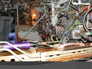
- 6. INTRODUCTION All aircraft, from the smallest trainers to the largest transports, have systems to direct the flow of fluids from their source to the units requiring them. These systems consist of hoses, tubing, fittings, and connectors and are often referred to as an aircraft's "plumbing." Even though aircraft fluid lines and related hardware are very reliable and require little maintenance, they cannot be overlooked.
- 7. An error in the selection or installation of a component could result in damage to a unit, loss of fluid, or complete system failure. Regular inspection and time-specified replacements ensure continuous and safe operation.
- 10. A single aircraft typically contains several different types of rigid fluid lines. Each type of line has a specific application. However, as a rule, rigid tubing is used in stationary applications and where long, relatively straight runs are possible. Systems that typically utilize rigid tubing include fuel, oil, oxygen, and instrument systems.
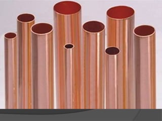
- 11. MATERIALS Many fluid lines used in early aircraft were made of copper tubing. However, copper tubing proved trouble- some because it became hard and brittle from the vibration encountered during flight, and eventually failed. To help prevent failures and extend the life of copper tubing, it must be periodically annealed to restore it to a soft condition.
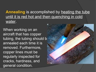
- 14. Annealing is accomplished by heating the tube until it is red hot and then quenching in cold water. When working on an aircraft that has copper tubing, the tubing should be annealed each time it is removed. Furthermore, copper lines must be regularly inspected for cracks, hardness, and general condition.
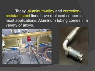
- 15. Today, aluminum-alloy and corrosion- resistant steel lines have replaced copper in most applications. Aluminum tubing comes in a variety of alloys.
- 16. For example, -in low pressure systems (below 1,000 psi) such as those used for instrument air or ventilating air, commercially pure aluminum tubing made from 1100-H14 (half-hard), or aluminum alloy 3003-H14 (half-hard) is used. -Low pressure fuel and oil and medium pressure (1,000 to 1,500 psi) hydraulic and pneumatic systems often use lines made of 5052-O aluminum alloy. This alloy, even in its annealed state, is about one and three-quarters times stronger than half-hard, commercially pure aluminum.
- 17. Occasionally, 2024-T aluminum alloy is used for fluid lines because of its higher strength. However, it is not as flexible and, therefore, is more difficult to bend and flare without cracking.
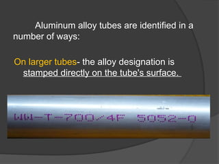
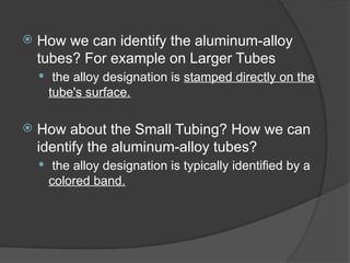
- 18. Aluminum alloy tubes are identified in a number of ways: On larger tubes- the alloy designation is stamped directly on the tube's surface.
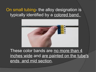
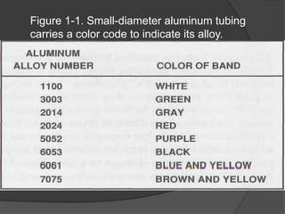
- 19. On small tubing- the alloy designation is typically identified by a colored band. These color bands are no more than 4 inches wide and are painted on the tube's ends and mid section.
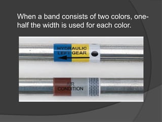
- 20. When a band consists of two colors, one- half the width is used for each color.
- 21. Figure 1-1. Small-diameter aluminum tubing carries a color code to indicate its alloy.
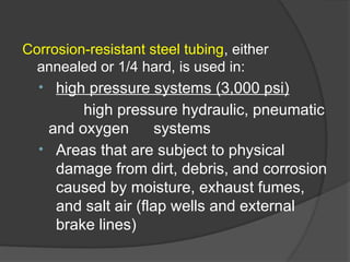
- 22. Corrosion-resistant steel tubing, either annealed or 1/4 hard, is used in: • high pressure systems (3,000 psi) high pressure hydraulic, pneumatic and oxygen systems • Areas that are subject to physical damage from dirt, debris, and corrosion caused by moisture, exhaust fumes, and salt air (flap wells and external brake lines)
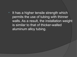
- 23. • It has a higher tensile strength which permits the use of tubing with thinner walls. As a result, the installation weight is similar to that of thicker-walled aluminum alloy tubing.
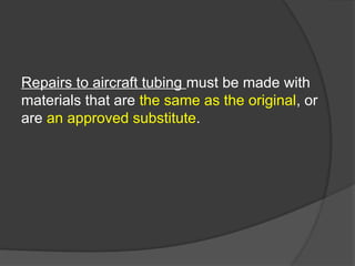
- 24. Repairs to aircraft tubing must be made with materials that are the same as the original, or are an approved substitute.
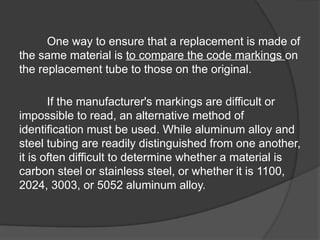
- 25. One way to ensure that a replacement is made of the same material is to compare the code markings on the replacement tube to those on the original. If the manufacturer's markings are difficult or impossible to read, an alternative method of identification must be used. While aluminum alloy and steel tubing are readily distinguished from one another, it is often difficult to determine whether a material is carbon steel or stainless steel, or whether it is 1100, 2024, 3003, or 5052 aluminum alloy.
- 26. For samples of tubing can be tested for: Hardness, Magnetic properties and Reaction to concentrated nitric acid.
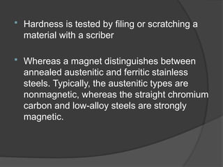
- 27. Hardness is tested by filing or scratching a material with a scriber Whereas a magnet distinguishes between annealed austenitic and ferritic stainless steels. Typically, the austenitic types are nonmagnetic, whereas the straight chromium carbon and low-alloy steels are strongly magnetic.
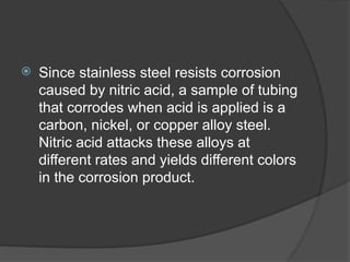
- 28. Since stainless steel resists corrosion caused by nitric acid, a sample of tubing that corrodes when acid is applied is a carbon, nickel, or copper alloy steel. Nitric acid attacks these alloys at different rates and yields different colors in the corrosion product.
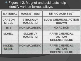
- 29. Figure 1-2. Magnet and acid tests help identify various ferrous alloys.
- 30. ANY QUESTIONS?
- 31. How we can identify the aluminum-alloy tubes? For example on Larger Tubes the alloy designation is stamped directly on the tube's surface. How about the Small Tubing? How we can identify the aluminum-alloy tubes? the alloy designation is typically identified by a colored band.
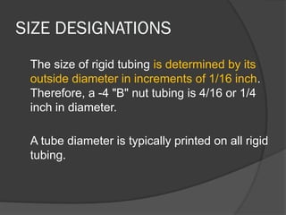
- 32. SIZE DESIGNATIONS The size of rigid tubing is determined by its outside diameter in increments of 1/16 inch. Therefore, a -4 "B" nut tubing is 4/16 or 1/4 inch in diameter. A tube diameter is typically printed on all rigid tubing.
- 33. Another important size designation is wall thickness, since this determines a tube's strength. Like the outside diameter, wall thickness is generally printed on the tube in thousandths of an inch.
- 34. One dimension that is not printed on rigid tubing is the inside diameter. However, since the outside diameter and wall thickness are indicated, the inside diameter is determined by subtracting twice the wall thickness from the outside diameter. For example, if you have a piece of -8 tubing with a wall thickness of 0.072 inches, you know the inside diameter is .356 inches, 0.5 - (2 x .072) = 0.356.
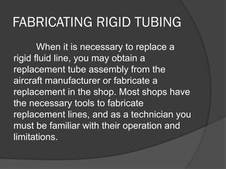
- 35. FABRICATING RIGID TUBING When it is necessary to replace a rigid fluid line, you may obtain a replacement tube assembly from the aircraft manufacturer or fabricate a replacement in the shop. Most shops have the necessary tools to fabricate replacement lines, and as a technician you must be familiar with their operation and limitations.
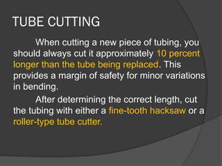
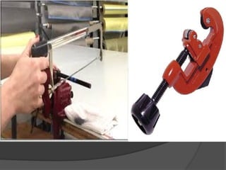
- 36. TUBE CUTTING When cutting a new piece of tubing, you should always cut it approximately 10 percent longer than the tube being replaced. This provides a margin of safety for minor variations in bending. After determining the correct length, cut the tubing with either a fine-tooth hacksaw or a roller-type tube cutter.
- 38. A tube cutter is most often used on soft metal tubing such as copper, aluminum, or aluminum alloy. However, they are not suitable for stainless-steel tubing because they tend to work harden the tube.
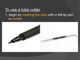
- 39. To use a tube cutter 1. begin by marking the tube with a felt-tip pen or scriber
- 40. 2. place the tubing in the cutting tool and align the cutting wheel with the cutting mark 3. Once aligned, gently tighten the cutting wheel onto the tube using the thumbscrew
- 41. 4. When the cutting wheel is snug, rotate the cutter around the tube and gradually increase pressure on the cutting wheel every 1 to 2 revolutions. NOTE: Be careful not to apply too much pressure at one time, as it could deform the tube or cause excessive burring.
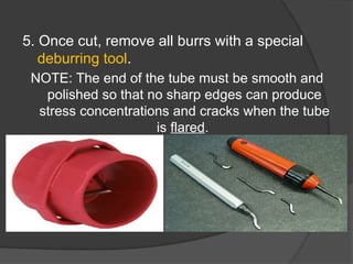
- 42. 5. Once cut, remove all burrs with a special deburring tool. NOTE: The end of the tube must be smooth and polished so that no sharp edges can produce stress concentrations and cracks when the tube is flared.
- 43. 6. After the tube has been cut and deburred, blow it out with compressed air to remove metal chips that could become imbedded in the tube.
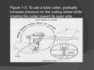
- 44. Figure 1-3. To use a tube cutter, gradually increase pressure on the cutting wheel while rotating the cutter toward its open side.
- 45. (2hrs)SUPERVISED PRACTICE: TUBE CUTTING MATERIALS Measuring tools Scriber/pen Tube cutter Deburring tools ¼ aluminum alloy/copper tube
- 47. ANY QUESTIONS?
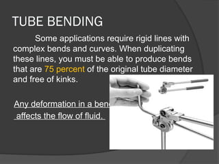
- 48. TUBE BENDING Some applications require rigid lines with complex bends and curves. When duplicating these lines, you must be able to produce bends that are 75 percent of the original tube diameter and free of kinks. Any deformation in a bend affects the flow of fluid.
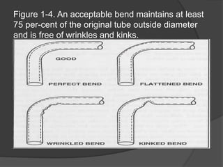
- 49. Figure 1-4. An acceptable bend maintains at least 75 per-cent of the original tube outside diameter and is free of wrinkles and kinks.
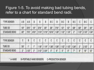
- 50. To help reduce the chance of making a bad bend, there are several charts that illustrate standard bend radii for different size tubes. The information on these charts should be adhered to closely.
- 51. Figure 1-5. To avoid making bad tubing bends, refer to a chart for standard bend radii.
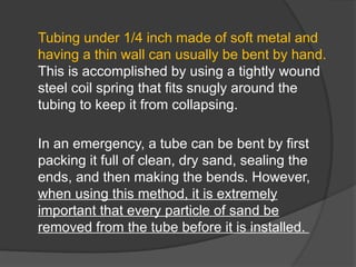
- 52. Tubing under 1/4 inch made of soft metal and having a thin wall can usually be bent by hand. This is accomplished by using a tightly wound steel coil spring that fits snugly around the tubing to keep it from collapsing. In an emergency, a tube can be bent by first packing it full of clean, dry sand, sealing the ends, and then making the bends. However, when using this method, it is extremely important that every particle of sand be removed from the tube before it is installed.
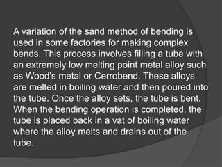
- 53. A variation of the sand method of bending is used in some factories for making complex bends. This process involves filling a tube with an extremely low melting point metal alloy such as Wood's metal or Cerrobend. These alloys are melted in boiling water and then poured into the tube. Once the alloy sets, the tube is bent. When the bending operation is completed, the tube is placed back in a vat of boiling water where the alloy melts and drains out of the tube.
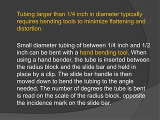
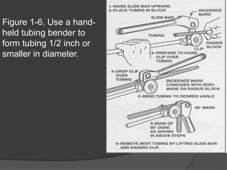
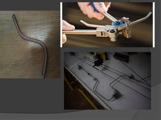
- 54. Tubing larger than 1/4 inch in diameter typically requires bending tools to minimize flattening and distortion. Small diameter tubing of between 1/4 inch and 1/2 inch can be bent with a hand bending tool. When using a hand bender, the tube is inserted between the radius block and the slide bar and held in place by a clip. The slide bar handle is then moved down to bend the tubing to the angle needed. The number of degrees the tube is bent is read on the scale of the radius block, opposite the incidence mark on the slide bar.
- 55. Figure 1-6. Use a hand- held tubing bender to form tubing 1/2 inch or smaller in diameter.
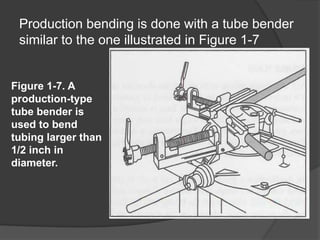
- 56. Production bending is done with a tube bender similar to the one illustrated in Figure 1-7 Figure 1-7. A production-type tube bender is used to bend tubing larger than 1/2 inch in diameter.
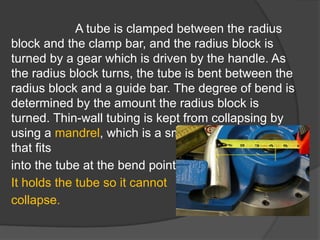
- 57. A tube is clamped between the radius block and the clamp bar, and the radius block is turned by a gear which is driven by the handle. As the radius block turns, the tube is bent between the radius block and a guide bar. The degree of bend is determined by the amount the radius block is turned. Thin-wall tubing is kept from collapsing by using a mandrel, which is a smooth round-end bar that fits into the tube at the bend point. It holds the tube so it cannot collapse.
- 58. 2HRS SUPERVISED PRACTICAL: TUBE BENDING MATERIALS Measuring tools Tube bending ¼ aluminum alloy or copper tube
- 60. ANY QUESTIONS?
- 61. ANY QUESTIONS?