Memristors and their potential applications 2012
Download as PPTX, PDF•4 likes•2,093 views

The document provides a comprehensive literature review on memristors, highlighting their properties, advantages, and various potential applications in programmable analog systems and artificial intelligence. Memristors offer benefits such as non-volatile memory, high data density, and low energy consumption, making them suitable for fields like signal processing, pattern recognition, and optimization problems. The review also discusses specific applications including programmable gain amplifiers, threshold comparators, relaxation oscillators, and their integration into artificial intelligence systems.


![References
[1] Blaise Mouttet, “Proposals for Memristor Crossbar Design and Applications”, Memristors and
Memristive Systems Symposium, UC Berkeley, Nov, 2008.
[2] S. Shin, K. Kim, and S.M. Kang, “Memristor Applications for Programmable Analog ICs”, IEEE
Tran. on Nanotech., vol. 10, no. 2, Mar 2011.
[3] Y. V. Pershin and M. D. Ventra, “Practical Approach to Programmable Analog Circuits With
Memristors” , IEEE Tran on Circuits & Systems, vol. 57, no. 8, Aug 2010.
[4] Yenpo Ho, Garng M. Huang and Peng Li, “Nonvolatile Memristor Memory: Device Characteristics
and Design Implications”, ICCAD’09, Nov 2–5, 2009, San Jose, California, USA.
[5] S. Kvatinsky, A. Kolodny and E. G. Friedman, “Memristor-based IMPLY Logic Design Procedure”,
ICCD '11 Proceedings, p.p. 142-147, 2011, USA
[6] D. B. Strukov, G. S. Snider, D. R. Stewart and R. S. Williams, “The missing memristor found”, Nature
Letters, vol 453, May, 2008.
[7] Chua, L. O., “Memristor - the missing circuit element”, IEEE Trans. Circuit Theory, 18, 507–519
(1971).](https://image.slidesharecdn.com/memristorstheirpotentialapplicationskafispresentation2012-150130230801-conversion-gate01/85/Memristors-and-their-potential-applications-2012-29-320.jpg)

Memristors and their potential applications 2012
- 1. Memristors & Their Potential Applications A Literature Review
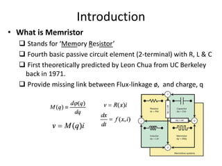
- 2. Introduction • What is Memristor Stands for ‘Memory Resistor’ Fourth basic passive circuit element (2-terminal) with R, L & C First theoretically predicted by Leon Chua from UC Berkeley back in 1971. Provide missing link between Flux-linkage ø, and charge, q
- 3. Introduction (Cont…) Properties of Memristor Function of amount of charge flowing through it. Can remember it’s last electrical state (Memristance) even if power is turned OFF. Voltage & current waves have same zero crossings (no phase shift between them) Pinched Hysteresis loop shrinks with increased in frequency, w Purely dissipative device, no storage of energy
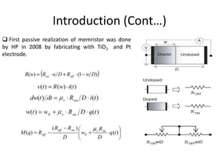
- 4. Introduction (Cont…) First passive realization of memristor was done by HP in 2008 by fabricating with TiO2 and Pt electrode.
- 5. Advantages of Memristor • Can work as both memory and logic functions • Higher data density due to nano-scale size • Requires less energy and dissipate less heat • Combines the jobs of working memory and hard drives into one tiny device (Non-volatile memory) • Faster and less expensive than MRAM • Provides greater reliability when power is interrupted in data centers • Would allow for a quicker boot up since information is not lost when the device is turned off • Can use anything between 0 and 1 (0.3, 0.8, 0.5, etc.) • Compatible with CMOS process and provide innovating nanotechnology due to the fact that it performs better the smaller it becomes.
- 6. Non-Volatile Memristor Memory 4 The concept of Universal Memory can be realized by using Memristor alone as it combines the advantages of both memories residing on top most and bottom of the hierarchy.
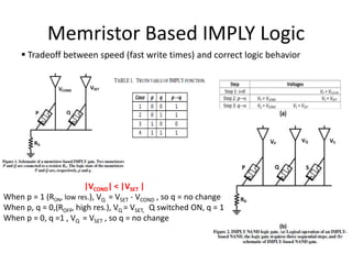
- 7. Memristor Based IMPLY Logic Tradeoff between speed (fast write times) and correct logic behavior |VCOND| < |VSET | When p = 1 (RON, low res.), VQ = VSET - VCOND , so q = no change When p, q = 0,(ROFF, high res.), VQ = VSET, Q switched ON, q = 1 When p = 0, q =1 , VQ = VSET , so q = no change
- 8. Potential Application #1 FPAAs (Field Programmable Analog Arrays)
- 9. FPAAs (Field Programmable Analog Arrays)1 Limitations of Conventional FPAAs: limited in the range of configurable states Lacks ability to electrically tune the resistance Solutions: By including memristor crossbar junctions in the input and feedback path of an op‐amp capacitor array, a transfer function can be tuned to adjust the gain, pole and/or zero of a filter. Advantages: Conversion between LPF and HPF by appropriate selection of ON/OFF states of Mij. Tuning of f‐3dB or pole/zero by adjustment of memristance state. Cascading multiple stages can provide for tunable band-pass adjustment Dynamic PID controllers can be implemented by connecting multiple stages in parallel.
- 10. Potential Application #2 Programmable Analog ICs 1) Fine-Resolution Programmable Resistor or Memristor- based digital potentiometer 2) Programmable Gain Amplifier 3) Programmable Threshold Comparator 4) Programmable Switching Thresholds Schmitt Trigger 5) Programmable Frequency Relaxation Oscillator
- 11. Fine-Resolution Programmable Resistor 2 Pulse-coded programmable resistor using a memristor. Need of a Programmable Resistor: In many high-frequency circuits such as amplifiers and filters, resistors need to be programmed for adaptation to particular applications or for compensation for PVT variations. Problems with Conventional Ones: In the switch-controlled resistors composed of an array of weighted resistors and switches used to realize such programmable resistor; the MOS switches typically introduce large parasitic capacitances and resistances. Furthermore, the parasitic values are dependent on the switch state. The state-dependent large parasitics limit the resolution and the number of bits of switching resistors. The usage of floating gate structures for realizing programmable resistor has long term reliability problems as the stored charge on the floating gate may slowly leak away with time. Advantages: • The most distinct feature of this memristor-based programmable resistor is that the resolution step of resistance can be adjusted with VPT, duty ratio, and ωPT. • Ease of programming and controllability due to the fact that memristance is programmed by patterning the pulse waveform. • The resistance programming with fine resolution and small parasitics is very useful in many midband and RF-range differential circuits.
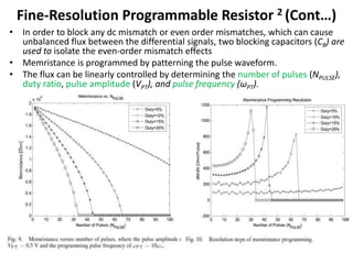
- 12. Fine-Resolution Programmable Resistor 2 (Cont…) • In order to block any dc mismatch or even order mismatches, which can cause unbalanced flux between the differential signals, two blocking capacitors (CB) are used to isolate the even-order mismatch effects • Memristance is programmed by patterning the pulse waveform. • The flux can be linearly controlled by determining the number of pulses (NPULSE), duty ratio, pulse amplitude (VPT), and pulse frequency (ωPT).
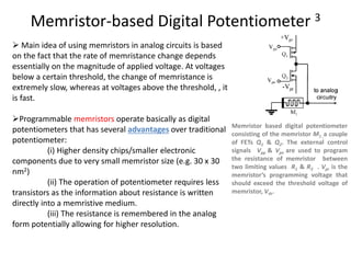
- 13. Memristor-based Digital Potentiometer 3 Main idea of using memristors in analog circuits is based on the fact that the rate of memristance change depends essentially on the magnitude of applied voltage. At voltages below a certain threshold, the change of memristance is extremely slow, whereas at voltages above the threshold, , it is fast. Programmable memristors operate basically as digital potentiometers that has several advantages over traditional potentiometer: (i) Higher density chips/smaller electronic components due to very small memristor size (e.g. 30 x 30 nm2) (ii) The operation of potentiometer requires less transistors as the information about resistance is written directly into a memristive medium. (iii) The resistance is remembered in the analog form potentially allowing for higher resolution. Memristor based digital potentiometer consisting of the memristor M1 ,a couple of FETs Q1 & Q2. The external control signals Vpp & Vpn are used to program the resistance of memristor between two limiting values R1 & R2 . Vpr is the memristor’s programming voltage that should exceed the threshold voltage of memristor, Vth.
- 14. Programmable Gain Amplifier 2 Circuit schematic of programmable gain amplifier using memristor, RL is the equivalent resistance of the pulse-programmed memristance Mid-band equivalent circuit, where Ci and Co are parasitic input and output capacitances, respectively. Features: Designed together with a 0.18-μm CMOS process and utilizing the memristor based programmable resistor With the memristor-based load resistance (RL ), the ac voltage gain is easily programmable by controlling the flux amount across the memristor This circuit becomes more advantageous when the application frequency is in the RF range, since the blocking capacitors can be integrated together with CMOS active devices for higher input frequencies. The mid-band ac voltage gain is Av = gm(ro || RL ) neglecting high-frequency effect of Ci & Co , where gm is diff transconductance of M1 &M2, ro is amplifier’s o/p impedance formed by M1∼M4
- 15. Programmable Gain Amplifier 3 (a) The Op-Amp A1 is connected in the standard non-inverting amplifier configuration with a memristor replacing a resistor. Two FETs (Q1/Q2) are used to program the resistance of the memristor thus selecting the amplifier gain. The capacitor C1 = 0.1 uF is used for noise suppression. (b) Programming of gain using 10-ms width pulses. In these measurements, the input voltage Vin =0.2 V is permanently supplied while positive and negative pulses change the state of memristor and correspondingly circuit’s gain. As a result, we observe a set of steps in the output signal. (c) Coarser control of gain using 20 ms width pulses. The gain of such amplifier is given by: The gain is determined by memristance RM which can be programmed between two limiting values Rmin & Rmax using two FETs. The desirable regime of operation that minimizes the voltage applied to the memristor is RM << R1 The amplifier’s gain is controlled using pulses of constant width. Longer pulses produce larger changes in allowing for coarser control of the gain (Fig c).
- 16. Programmable Threshold Comparator 3 (a) Schematics of a programmable threshold comparator. Here R1 = 10 kΩ and A1 is an operational amplifier. (b) Programmable threshold comparator response to the input voltage Vin = Vosin(2πft) with Vo = 1.3 V & f = 1 Hz, and several negative programming pulses of 10 ms width applied in the time interval between 4 and 8 seconds. Each 10 ms voltage pulse changes RM by approximately 430 Ω causing a gradual decrease of the comparator threshold. It involves the memristor-based digital potentiometer block The comparator threshold is determined by the voltage on the memristor given by If the signal amplitude at the positive input exceeds, then output signal is equal to the saturation voltage of the operational amplifier (which in the present case is close to V). In the opposite case, is close to 2.5 V.
- 17. Programmable Switching Thresholds Schmitt Trigger 3 (a) Schematics of a programmable switching thresholds Schmitt trigger with memristor. Here, R1 = 10 kΩ. (b) Programmable switching thresholds Schmitt trigger response to the input voltage Vin = Vo sin(2πft) with Vo = 1.3 V & f = 1 Hz, and several positive programming pulses of 10 ms width applied in the time interval between 2 and 4 s. It involves the memristor-based digital potentiometer block This circuit behaves as an inverted comparator with the switching thresholds given by When we apply programming pulses to M1, its resistance RMchanges as well as the switching thresholds of Schmitt trigger.
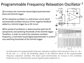
- 18. Programmable Frequency Relaxation Oscillator 3 (a) Schematics of a programmable frequency relaxation oscillator with memristor. Here, R1 = R2 = 10 kΩ and C1 = 10 µF. (b) Oscillating signals in the different points of the programmable frequency relaxation oscillator. The lower panel demonstrates an increase in the oscillation frequency as RM is decreased by several negative pulses applied to V+ . It involves the memristor-based digital potentiometer block and Schmitt trigger. The relaxation oscillator is a well-known circuit which automatically oscillates because of the negative feedback added to a Schmitt trigger by an RC circuit. The period of oscillations is determined by both the RC components and switching thresholds of the Schmitt trigger. Therefore, in order to control the relaxation oscillator frequency, a memristor-based digital potentiometer is used to vary switching thresholds of the Schmitt trigger.
- 19. Potential Application #3 Programmable Drive Waveforms
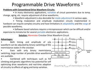
- 20. Programmable Drive Waveforms 1 Assuming RLOW of memristors << RF, R Problems with Conventional Drive Waveform Circuits: • In many electronics applications, variation of circuit parameters due to temp. change, aging, etc. require adjustment of drive waveforms. • Waveform adjustment is also desirable for mode adjustment in various apps. • Timing modulation and amplitude modulation circuits implemented in hardware can require complex circuitry and have limitations in adaptability and the range of possible waveforms. • Software based solutions require a microprocessor which can be difficult and/or expensive to miniaturize for several portable electronics applications. Solution: Memristor Crossbar Drive Waveform Circuit Advantages: • Both timing and amplitude of o/p waveform can be adjusted by binary switching of the memristance states in the crossbar. • Even with only binary memristance switching, large number of possible drive waveforms are available. • Combined with techniques such as hill climbing and genetic algorithms has potential for self optimizing drive waveforms and real‐time adaption of circuitry to effects of aging and temp variation.
- 21. Potential Application #4 Pattern Recognition
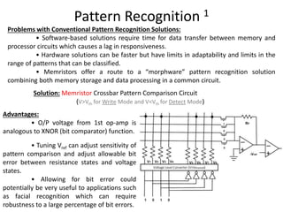
- 22. Pattern Recognition 1 Advantages: • O/P voltage from 1st op‐amp is analogous to XNOR (bit comparator) function. • Tuning Vref can adjust sensitivity of pattern comparison and adjust allowable bit error between resistance states and voltage states. • Allowing for bit error could potentially be very useful to applications such as facial recognition which can require robustness to a large percentage of bit errors. Problems with Conventional Pattern Recognition Solutions: • Software‐based solutions require time for data transfer between memory and processor circuits which causes a lag in responsiveness. • Hardware solutions can be faster but have limits in adaptability and limits in the range of patterns that can be classified. • Memristors offer a route to a “morphware” pattern recognition solution combining both memory storage and data processing in a common circuit. Solution: Memristor Crossbar Pattern Comparison Circuit (V>Vth for Write Mode and V<Vth for Detect Mode)
- 23. Potential Application #5 Arithmetic Optimization Problems
- 24. Arithmetic Optimization Problems 1 Problems with Conventional Arithmetic Processor Designs : • Segmentation between memory and processor circuitry may produce a bottleneck in speed. New clock independent designs are desirable. • Logic based arithmetic is inefficient for some network optimization problems involving repeated recalculation of sums Assuming RLOW of memristors << R/8 Analog output representative of 2+4 Solution: Memristor Crossbar Arithmetic Circuit Advantages: • Although op‐amps are slower than logic circuits, the combination of memory and processing in a single circuit reduces the reliance on a clock. • May be scalable to provide real time solutions to network optimization.
- 25. Potential Application #6 Signal Mixing
- 26. Signal Mixing Problems with Conventional Modulation Systems: • Increase in portable wireless electronics requires more efficient uses of spectrum with techniques such as frequency hopping. • Simpler but more secure signal encryption methods are desirable. Solution: Back‐to‐back diode memristor crossbar Equivalent circuit at each crossbar junction For VinB less than the diode threshold voltage, the resistance state of Mij and voltage state of VinA can be used to modulate signal transmission. Advantages: • Switching of carrier frequencies allow more efficient use of spectrum and compensation for crowded channels. • Potential exist for improved signal encryption by sharing a randomized memristance switching pattern between sender and receiver. Input Wiring
- 27. Potential Application #7 Artificial Intelligence
- 28. Artificial Intelligence Potential Routes to Strong A.I. with Memristor Crossbars: • Neural Networks (feed-forward of nonlinear weighted sums of memristance states) • Genetic Algorithms (selection, crossover, and mutation of memristance states) • Emergent Complexity from Memory‐Prediction Framework (Hawkins approach) • Fuzzy Logic implementation Memristor Crossbar Circuit Design for Sensor Stimulated Emergent Behavior
- 29. References [1] Blaise Mouttet, “Proposals for Memristor Crossbar Design and Applications”, Memristors and Memristive Systems Symposium, UC Berkeley, Nov, 2008. [2] S. Shin, K. Kim, and S.M. Kang, “Memristor Applications for Programmable Analog ICs”, IEEE Tran. on Nanotech., vol. 10, no. 2, Mar 2011. [3] Y. V. Pershin and M. D. Ventra, “Practical Approach to Programmable Analog Circuits With Memristors” , IEEE Tran on Circuits & Systems, vol. 57, no. 8, Aug 2010. [4] Yenpo Ho, Garng M. Huang and Peng Li, “Nonvolatile Memristor Memory: Device Characteristics and Design Implications”, ICCAD’09, Nov 2–5, 2009, San Jose, California, USA. [5] S. Kvatinsky, A. Kolodny and E. G. Friedman, “Memristor-based IMPLY Logic Design Procedure”, ICCD '11 Proceedings, p.p. 142-147, 2011, USA [6] D. B. Strukov, G. S. Snider, D. R. Stewart and R. S. Williams, “The missing memristor found”, Nature Letters, vol 453, May, 2008. [7] Chua, L. O., “Memristor - the missing circuit element”, IEEE Trans. Circuit Theory, 18, 507–519 (1971).
- 30. Thank You Q & A