SlideShare a Scribd company logo
14G MOTOR GRADER
96U00001-01097
Note: Use Bookmarks panel to navigate
Printed by Heavy Equipment Manuals Printed in U.S.A
v2.20
Heavy Equipment Manuals
This is the sample of the sample
click on the download link for
complete manual
For some reason if link deos not work
download this pdf and then click
DOWNLOAD LINK
 
 
 
 
 
 
 
 
 
 
 

 
 
 
 

 
 
 
 
 

 
 

 
 
 
 
 
 


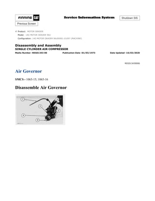
Product: MOTOR GRADER
Model: 14G MOTOR GRADER 96U
Configuration: 14G MOTOR GRADER 96U00001-01097 (MACHINE)
Disassembly and Assembly
SINGLE CYLINDER AIR COMPRESSOR
Media Number -REG01343-00 Publication Date -01/03/1973 Date Updated -10/03/2020
REG013430006
Air Governor
SMCS - 1065-15; 1065-16
Disassemble Air Governor
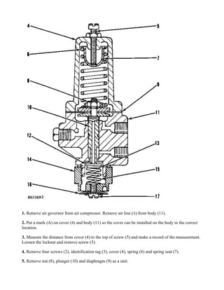
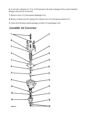
1. Remove air governor from air compressor. Remove air line (1) from body (11).
2. Put a mark (A) on cover (4) and body (11) so the cover can be installed on the body in the correct
location.
3. Measure the distance from cover (4) to the top of screw (5) and make a record of the measurement.
Loosen the locknut and remove screw (5).
4. Remove four screws (2), identification tag (3), cover (4), spring (6) and spring seat (7).
5. Remove nut (8), plunger (10) and diaphragm (9) as a unit.
6. A rod with a diameter of .12 in. (3.05 mm) put in the hole in plunger (10) is used to hold the
plunger when nut (8) is removed.
7. Remove screw (17) and exhaust diaphragm (16).
8. Remove exhaust nut (14), spring (15), exhaust valve (12) and spring retainer (13).
9. Clean all of the parts and the passages in body (11) and plunger (10).
Assemble Air Governor
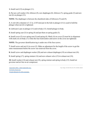
1. Install seal (12) on plunger (11).
2. Put new soft washer (10), follower (9), new diaphragm (8), follower (7), spring guide (5) and new
nut (6) on plunger (11).
NOTE: The diaphragm is between the chamfered sides of followers (7) and (9).
3. A rod with a diameter of .12 in. (3.05 mm) put in the hole in plunger (11) is used to hold the
plunger when nut (6) is tightened.
4. Lubricant is put on plunger (11) and in body (13). Install plunger in body.
5. Install spring seat (3) in spring (4) and put them on spring guide (5).
6. Install cover (2) over spring seat (3) and spring (4). Mark (A) on cover (2) must be in alignment
with mark (A) on body (11) when the four lockwashers and screws in the cover are tightened.
NOTE: The governor identification tag is under one of the four screws.
7. Install screw and nut (1) in cover (2). Make an adjustment for the length of the screw to get the
same measurement before the screw was removed from the cover.
8. Install screw and diaphragm washer (20) and new exhaust diaphragm (19) on exhaust nut (18).
9. Install spring (17), spring retainer (16) and new exhaust valve (15) in exhaust nut (18).
10. Install washer (14) and exhaust nut (18), spring retainer and spring in body (13). Install air
governor and air line on air compressor.
Copyright 1993 - 2024 Caterpillar Inc.
All Rights Reserved.
Private Network For SIS Licensees.
Sun Sep 15 00:40:26 UTC+0530 2024


Product: MOTOR GRADER
Model: 14G MOTOR GRADER 96U
Configuration: 14G MOTOR GRADER 96U00001-01097 (MACHINE)
Disassembly and Assembly
SINGLE CYLINDER AIR COMPRESSOR
Media Number -REG01343-00 Publication Date -01/03/1973 Date Updated -10/03/2020
REG013430005
Crankshaft
SMCS - 1065-11; 1065-12
Remove Crankshaft
start by:
a) remove head assembly
b) remove piston and rod
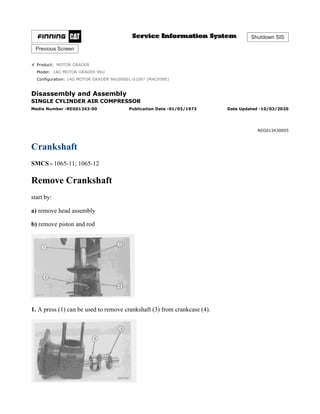
1. A press (1) can be used to remove crankshaft (3) from crankcase (4).
2. Put a pipe (2), with a bore larger than 1.03 in. (26.2 mm) and a diameter of approximately 2 in.
(50.8 mm) with an approximate length of 6 in. (152.4 mm), over the end of crankshaft (3) and on
bearing (5).
3. Push crankshaft (3) and bearing (5) out of crankcase (4) as a unit.
4. Remove bearing (5).
Install Crankshaft
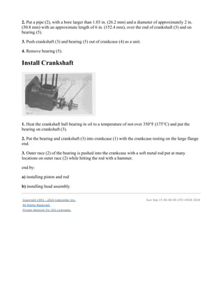
1. Heat the crankshaft ball bearing in oil to a temperature of not over 350°F (175°C) and put the
bearing on crankshaft (3).
2. Put the bearing and crankshaft (3) into crankcase (1) with the crankcase resting on the large flange
end.
3. Outer race (2) of the bearing is pushed into the crankcase with a soft metal rod put at many
locations on outer race (2) while hitting the rod with a hammer.
end by:
a) installing piston and rod
b) installing head assembly
Copyright 1993 - 2024 Caterpillar Inc.
All Rights Reserved.
Private Network For SIS Licensees.
Sun Sep 15 00:40:05 UTC+0530 2024


Product: MOTOR GRADER
Model: 14G MOTOR GRADER 96U
Configuration: 14G MOTOR GRADER 96U00001-01097 (MACHINE)
Disassembly and Assembly
SINGLE CYLINDER AIR COMPRESSOR
Media Number -REG01343-00 Publication Date -01/03/1973 Date Updated -10/03/2020
REG013430003
Head Assembly
SMCS - 1065-11; 1065-12; 1065-17
Remove Head Assembly
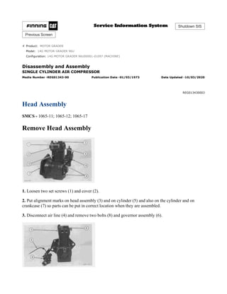
1. Loosen two set screws (1) and cover (2).
2. Put alignment marks on head assembly (3) and on cylinder (5) and also on the cylinder and on
crankcase (7) so parts can be put in correct location when they are assembled.
3. Disconnect air line (4) and remove two bolts (8) and governor assembly (6).
4. Remove four nuts (9) and remove head assembly (3).
NOTE: If needed, hit head assembly (3) with a soft hammer and then remove the head assembly.
Install Head Assembly
1. Install new gasket (4) on cylinder (2).
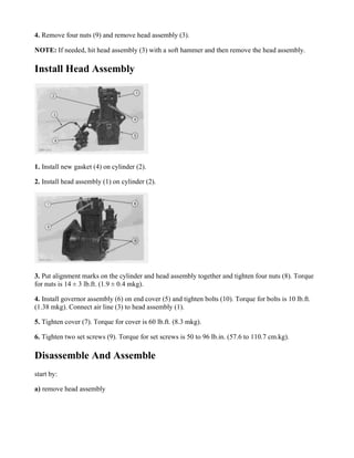
2. Install head assembly (1) on cylinder (2).
3. Put alignment marks on the cylinder and head assembly together and tighten four nuts (8). Torque
for nuts is 14 ± 3 lb.ft. (1.9 ± 0.4 mkg).
4. Install governor assembly (6) on end cover (5) and tighten bolts (10). Torque for bolts is 10 lb.ft.
(1.38 mkg). Connect air line (3) to head assembly (1).
5. Tighten cover (7). Torque for cover is 60 lb.ft. (8.3 mkg).
6. Tighten two set screws (9). Torque for set screws is 50 to 96 lb.in. (57.6 to 110.7 cm.kg).
Disassemble And Assemble
start by:
a) remove head assembly
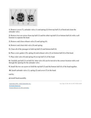
1. Remove cover (7), unloader valve (1) and spring (2) from top half (3) of head and clean the
unloader valve.
2. Remove two set screws from top half (3) and hit either top half (3) or bottom half (4) with a soft
hammer to separate the head.
3. Remove and clean exhaust valve (5) and spring (6).
4. Remove and clean inlet valve (8) and spring.
5. Clean all of the passages in both top half (3) and bottom half (4).
6. Place a new gasket (10), spring (6) and exhaust valve (5) on bottom half (4) of the head.
7. Place inlet valve (8) and spring (9) on top half (3) of the head.
8. Carefully put half (3) on half (4). Inlet valve (8) can be moved to the correct location with a rod
through the opening for the unloader valve.
9. Install the two set screws to hold the top half (3) and the bottom half (4) of the head together.
10. Install unloader valve (1), spring (2) and cover (7) in the head.
end by:
a) install head assembly
Copyright 1993 - 2024 Caterpillar Inc.
All Rights Reserved.
Private Network For SIS Licensees.
Sun Sep 15 00:39:31 UTC+0530 2024


Product: MOTOR GRADER
Model: 14G MOTOR GRADER 96U
Configuration: 14G MOTOR GRADER 96U00001-01097 (MACHINE)
Disassembly and Assembly
SINGLE CYLINDER AIR COMPRESSOR
Media Number -REG01343-00 Publication Date -01/03/1973 Date Updated -10/03/2020
REG013430004
Piston And Rod
SMCS - 1065-11; 1065-12
Piston And Rod Removal
start by:
a) remove head assembly
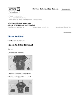
1. Remove cylinder (1) and gasket (2).
2. Remove bolts (3) and end cover (4).
This is the sample of the sample
click on the download link for
complete manual
For some reason if link deos not work
download this pdf and then click
DOWNLOAD LINK
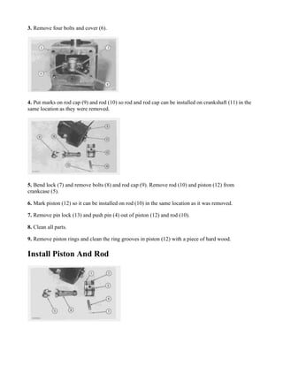
3. Remove four bolts and cover (6).
4. Put marks on rod cap (9) and rod (10) so rod and rod cap can be installed on crankshaft (11) in the
same location as they were removed.
5. Bend lock (7) and remove bolts (8) and rod cap (9). Remove rod (10) and piston (12) from
crankcase (5).
6. Mark piston (12) so it can be installed on rod (10) in the same location as it was removed.
7. Remove pin lock (13) and push pin (4) out of piston (12) and rod (10).
8. Clean all parts.
9. Remove piston rings and clean the ring grooves in piston (12) with a piece of hard wood.
Install Piston And Rod
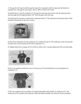
1. The gap for oil ring (1) and the gap for rings (2) is measured with the rings near the bottom in
cylinder (12). The gap for each ring is .003 to .009 in. (0.08 to 0.23 mm).
2. Install rings (1) and (2) on piston (3). The gap for each ring must not be near the piston pin bore
and each gap must be approximately 120° from the gap in the next ring.
3. Install pin (4) in piston (3) and rod (6). Install pin lock (7). The mark put on the piston shows if the
location of the piston on the rod is correct.
4. Put rod (6) and piston (3) into crankcase (11). Install rod cap (5). The marks put on the rod cap and
rod show the correct location of the rod in crankcase (11).
5. Tighten bolts (9) to a torque of 35 to 40 lb.in. (40.6 to 46.1 cm.kg). Bend lock (10) over bolt heads.
6. Put a new gasket on both end cover (13) and cover (15) and install the covers and gaskets on
crankcase (11).
7. Put a new gasket (14) on cylinder (12) and put the gasket and cylinder on crankcase (11). The
marks put on the cylinder and crankcase, before the head assembly was removed, must be together.
end by:
a) install head assembly
Copyright 1993 - 2024 Caterpillar Inc.
All Rights Reserved.
Private Network For SIS Licensees.
Sun Sep 15 00:39:46 UTC+0530 2024
 
 
 
 
 
 
 
 
 
 
 
 
 
 
 
 
 
 
 
 
 
 
 
 
 
 
 
 
 
 
 
 
 
 
 
 
 
 
 
 
 
 
 
 
 
 
 
 
 
 
 
 
 
 
 
 
 
 
 
 
 


Product: MOTOR GRADER
Model: 14G MOTOR GRADER 96U
Configuration: 14G MOTOR GRADER 96U00001-01097 (MACHINE)
Disassembly and Assembly
14G MOTOR GRADER VEHICLE SYSTEMS
Media Number -REG01699-02 Publication Date -01/08/1980 Date Updated -10/10/2001
Air Tank
SMCS - 4272-11; 4272-12
Remove Air Tank
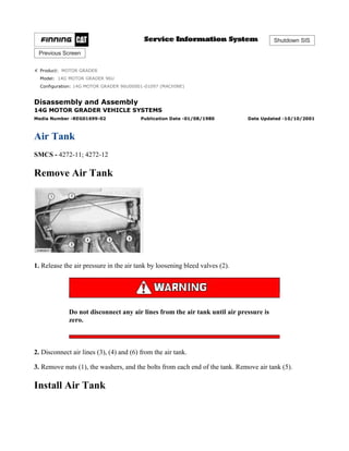
1. Release the air pressure in the air tank by loosening bleed valves (2).
Do not disconnect any air lines from the air tank until air pressure is
zero.
2. Disconnect air lines (3), (4) and (6) from the air tank.
3. Remove nuts (1), the washers, and the bolts from each end of the tank. Remove air tank (5).
Install Air Tank
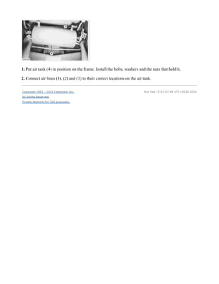
1. Put air tank (4) in position on the frame. Install the bolts, washers and the nuts that hold it.
2. Connect air lines (1), (2) and (3) to their correct locations on the air tank.
Copyright 1993 - 2024 Caterpillar Inc.
All Rights Reserved.
Private Network For SIS Licensees.
Sun Sep 15 01:03:48 UTC+0530 2024


Product: MOTOR GRADER
Model: 14G MOTOR GRADER 96U
Configuration: 14G MOTOR GRADER 96U00001-01097 (MACHINE)
Disassembly and Assembly
14G MOTOR GRADER VEHICLE SYSTEMS
Media Number -REG01699-02 Publication Date -01/08/1980 Date Updated -10/10/2001
Articulation Cylinders
SMCS - 7058-11; 7058-12
Remove Articulation Cylinders
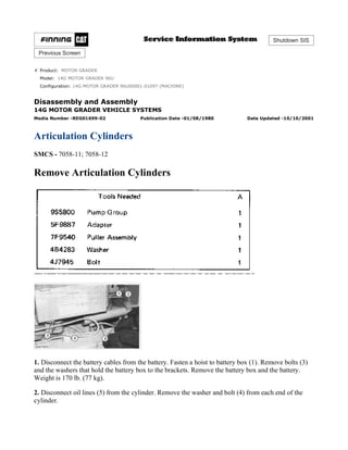
1. Disconnect the battery cables from the battery. Fasten a hoist to battery box (1). Remove bolts (3)
and the washers that hold the battery box to the brackets. Remove the battery box and the battery.
Weight is 170 lb. (77 kg).
2. Disconnect oil lines (5) from the cylinder. Remove the washer and bolt (4) from each end of the
cylinder.
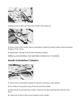
3. Remove pins (2) from each end of the cylinder with tooling (A).
4. Fasten a hoist to the cylinder. Remove articulation cylinder (6) and the washers from the machine.
Weight is 76 lb. (34 kg).
5. Repeat Steps 1 through 4 for the other articulation cylinder.
NOTE: See DISASSEMBLE AND ASSEMBLE HYDRAULIC CYLINDERS.
Install Articulation Cylinders
1. Fasten a hoist to articulation cylinder (1) and put it in position on the machine.
2. Put washers (2) in position on top of the rod end of the cylinder.
3. Install the pin in each end of the cylinder. Install the bolt and washer that hold each pin to the
frame.
4. Connect the oil lines to their correct locations on the cylinder.
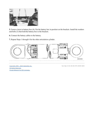
5. Fasten a hoist to battery box (4). Put the battery box in position on the brackets. Install the washers
and bolts (3) that hold the battery box to the brackets.
6. Connect the battery cables to the battery.
7. Repeat Steps 1 through 6 for the other articulation cylinder.
Copyright 1993 - 2024 Caterpillar Inc.
All Rights Reserved.
Private Network For SIS Licensees.
Sun Sep 15 01:04:40 UTC+0530 2024


Product: MOTOR GRADER
Model: 14G MOTOR GRADER 96U
Configuration: 14G MOTOR GRADER 96U00001-01097 (MACHINE)
Disassembly and Assembly
14G MOTOR GRADER VEHICLE SYSTEMS
Media Number -REG01699-02 Publication Date -01/08/1980 Date Updated -10/10/2001
Articulation Lock Check Valve, Blade Lift Lock Check Valve
SMCS - 5235-11; 5235-12
Remove Articulation Lock Check Valve
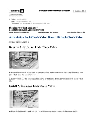
1. Put identification on all oil lines as to their location on the lock check valve. Disconnect oil lines
(1) and (2) from the lock check valve.
2. Remove bolts (3) that hold lock check valve to the frame. Remove articulation lock check valve
(4).
Install Articulation Lock Check Valve
1. Put articulation lock check valve (1) in position on the frame. Install the bolts that hold it.
2. Connect oil lines (2) and (3) to their correct locations on the valve.
Remove Blade Lift Lock Check Valve
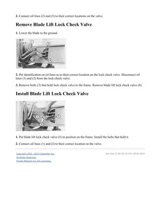
1. Lower the blade to the ground.
2. Put identification on oil lines as to their correct location on the lock check valve. Disconnect oil
lines (1) and (2) from the lock check valve.
3. Remove bolts (3) that hold lock check valve to the frame. Remove blade lift lock check valve (4).
Install Blade Lift Lock Check Valve
1. Put blade lift lock check valve (3) in position on the frame. Install the bolts that hold it.
2. Connect oil lines (1) and (2) to their correct location on the valve.
Copyright 1993 - 2024 Caterpillar Inc.
All Rights Reserved.
Private Network For SIS Licensees.
Sun Sep 15 00:45:35 UTC+0530 2024


Product: MOTOR GRADER
Model: 14G MOTOR GRADER 96U
Configuration: 14G MOTOR GRADER 96U00001-01097 (MACHINE)
Disassembly and Assembly
14G MOTOR GRADER VEHICLE SYSTEMS
Media Number -REG01699-02 Publication Date -01/08/1980 Date Updated -10/10/2001
Ball And Socket Joint Inserts (Earlier)
SMCS - 5102-11; 5102-12
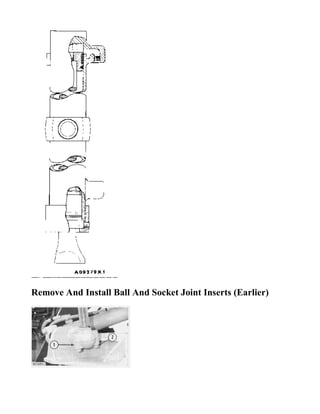
Remove And Install Ball And Socket Joint Inserts (Earlier)
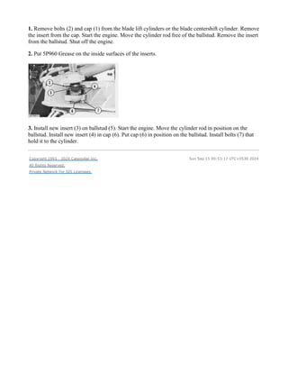
1. Remove bolts (2) and cap (1) from the blade lift cylinders or the blade centershift cylinder. Remove
the insert from the cap. Start the engine. Move the cylinder rod free of the ballstud. Remove the insert
from the ballstud. Shut off the engine.
2. Put 5P960 Grease on the inside surfaces of the inserts.
3. Install new insert (3) on ballstud (5). Start the engine. Move the cylinder rod in position on the
ballstud. Install new insert (4) in cap (6). Put cap (6) in position on the ballstud. Install bolts (7) that
hold it to the cylinder.
Copyright 1993 - 2024 Caterpillar Inc.
All Rights Reserved.
Private Network For SIS Licensees.
Sun Sep 15 00:53:17 UTC+0530 2024
This is the sample of the sample
click on the download link for
complete manual
For some reason if link deos not work
download this pdf and then click
DOWNLOAD LINK

More Related Content

PDF
caya-cayb-cayc-1-6-tdi-cr-engine-eng.pdf
AnhPhan363296
 
PDF
Caterpillar cat 130 g motor grader (prefix 74v) service repair manual (74v000...
dkdmidkkdk
 
PDF
Caterpillar cat 130 g motor grader (prefix 74v) service repair manual (74v000...
fjsekdmmeed
 
PDF
Caterpillar cat 130 g motor grader (prefix 74v) service repair manual (74v000...
fjjsekkdmme
 
PDF
Caterpillar cat 130 g motor grader (prefix 74v) service repair manual (74v005...
fjsekdmmeed
 
PDF
Caterpillar cat 130 g motor grader (prefix 74v) service repair manual (74v005...
fjjsekkdmme
 
PDF
Caterpillar cat 160 h motor grader (prefix 9ej) service repair manual (9ej000...
ufdjskeksmemzx
 
PDF
Caterpillar cat 160 h motor grader (prefix 9ej) service repair manual (9ej000...
fiksfejjsekkmme
 
caya-cayb-cayc-1-6-tdi-cr-engine-eng.pdf
AnhPhan363296
 
Caterpillar cat 130 g motor grader (prefix 74v) service repair manual (74v000...
dkdmidkkdk
 
Caterpillar cat 130 g motor grader (prefix 74v) service repair manual (74v000...
fjsekdmmeed
 
Caterpillar cat 130 g motor grader (prefix 74v) service repair manual (74v000...
fjjsekkdmme
 
Caterpillar cat 130 g motor grader (prefix 74v) service repair manual (74v005...
fjsekdmmeed
 
Caterpillar cat 130 g motor grader (prefix 74v) service repair manual (74v005...
fjjsekkdmme
 
Caterpillar cat 160 h motor grader (prefix 9ej) service repair manual (9ej000...
ufdjskeksmemzx
 
Caterpillar cat 160 h motor grader (prefix 9ej) service repair manual (9ej000...
fiksfejjsekkmme
 

Similar to caterpillar 14g motor grader service manual (20)

PPT
Ohv.reassembly
Muhammad Nakir
 
PDF
Caterpillar cat 130 g motor grader (prefix 74v) service repair manual (74v020...
fjsekdmmeed
 
PDF
Caterpillar cat 130 g motor grader (prefix 74v) service repair manual (74v020...
fjjsekkdmme
 
PDF
Caterpillar cat 120 g motor grader (prefix 87v) service repair manual (87v083...
fjsekkdmmmse
 
PDF
Caterpillar cat 120 g motor grader (prefix 87v) service repair manual (87v083...
fjsjjekdkme
 
PDF
Caterpillar Cat 650B and 660B WHEEL TRACTOR (Prefix 58K) Service Repair Manua...
9fikslkddmd8u
 
PDF
Caterpillar Cat 650B and 660B WHEEL TRACTOR (Prefix 58K) Service Repair Manua...
8foskkdjdkdm3e
 
PDF
Caterpillar Cat 650B and 660B WHEEL TRACTOR (Prefix 58K) Service Repair Manua...
shibi1322
 
PDF
Caterpillar Cat 980F WHEEL LOADER (Prefix 5XJ) Service Repair Manual (5XJ0071...
a9ekdodkdkd
 
PDF
Caterpillar Cat 980F WHEEL LOADER (Prefix 5XJ) Service Repair Manual (5XJ0071...
f8usueijdmm
 
PDF
Caterpillar Cat 980F WHEEL LOADER (Prefix 5XJ) Service Repair Manual Instant ...
onyvzcwadtu05
 
PDF
Caterpillar Cat 980F WHEEL LOADER (Prefix 5XJ) Service Repair Manual (5XJ0071...
tuj661406
 
PDF
Caterpillar Cat 980F WHEEL LOADER (Prefix 5XJ) Service Repair Manual (5XJ0071...
fusjekddud3e
 
PDF
Caterpillar Cat 980F WHEEL LOADER (Prefix 5XJ) Service Repair Manual (5XJ0071...
jiaozhao12657
 
PDF
Caterpillar Cat 980F WHEEL LOADER (Prefix 5XJ) Service Repair Manual Instant ...
ze3xiandiao
 
PDF
Caterpillar Cat 980F WHEEL LOADER (Prefix 5XJ) Service Repair Manual (5XJ0071...
fjkskkedmm4r
 
PDF
Caterpillar Cat 980F WHEEL LOADER (Prefix 5XJ) Service Repair Manual (5XJ0071...
shuangminzou
 
PDF
Caterpillar cat 16 g motor grader (prefix 93u) service repair manual (93u0267...
dkdmidkkdk
 
PDF
Caterpillar cat 16 g motor grader (prefix 93u) service repair manual (93u0267...
fjjsekkdmme
 
PDF
Caterpillar cat 16 g motor grader (prefix 93u) service repair manual (93u0267...
fjsekdmmeed
 
Ohv.reassembly
Muhammad Nakir
 
Caterpillar cat 130 g motor grader (prefix 74v) service repair manual (74v020...
fjsekdmmeed
 
Caterpillar cat 130 g motor grader (prefix 74v) service repair manual (74v020...
fjjsekkdmme
 
Caterpillar cat 120 g motor grader (prefix 87v) service repair manual (87v083...
fjsekkdmmmse
 
Caterpillar cat 120 g motor grader (prefix 87v) service repair manual (87v083...
fjsjjekdkme
 
Caterpillar Cat 650B and 660B WHEEL TRACTOR (Prefix 58K) Service Repair Manua...
9fikslkddmd8u
 
Caterpillar Cat 650B and 660B WHEEL TRACTOR (Prefix 58K) Service Repair Manua...
8foskkdjdkdm3e
 
Caterpillar Cat 650B and 660B WHEEL TRACTOR (Prefix 58K) Service Repair Manua...
shibi1322
 
Caterpillar Cat 980F WHEEL LOADER (Prefix 5XJ) Service Repair Manual (5XJ0071...
a9ekdodkdkd
 
Caterpillar Cat 980F WHEEL LOADER (Prefix 5XJ) Service Repair Manual (5XJ0071...
f8usueijdmm
 
Caterpillar Cat 980F WHEEL LOADER (Prefix 5XJ) Service Repair Manual Instant ...
onyvzcwadtu05
 
Caterpillar Cat 980F WHEEL LOADER (Prefix 5XJ) Service Repair Manual (5XJ0071...
tuj661406
 
Caterpillar Cat 980F WHEEL LOADER (Prefix 5XJ) Service Repair Manual (5XJ0071...
fusjekddud3e
 
Caterpillar Cat 980F WHEEL LOADER (Prefix 5XJ) Service Repair Manual (5XJ0071...
jiaozhao12657
 
Caterpillar Cat 980F WHEEL LOADER (Prefix 5XJ) Service Repair Manual Instant ...
ze3xiandiao
 
Caterpillar Cat 980F WHEEL LOADER (Prefix 5XJ) Service Repair Manual (5XJ0071...
fjkskkedmm4r
 
Caterpillar Cat 980F WHEEL LOADER (Prefix 5XJ) Service Repair Manual (5XJ0071...
shuangminzou
 
Caterpillar cat 16 g motor grader (prefix 93u) service repair manual (93u0267...
dkdmidkkdk
 
Caterpillar cat 16 g motor grader (prefix 93u) service repair manual (93u0267...
fjjsekkdmme
 
Caterpillar cat 16 g motor grader (prefix 93u) service repair manual (93u0267...
fjsekdmmeed
 
Ad

More from Heavy Equipment Manual (20)

PDF
SAA4D95LE-7A KOMATSU ENGINE PARTS MANUAL SN 800001-UP (For PC138US-11PC138USL...
Heavy Equipment Manual
 
PDF
PC1400-1 KOMATSU Hydraulic Mining Shovels Parts Manual
Heavy Equipment Manual
 
PDF
SK07J-2 Komatsu Skid Steer Loader Parts Manual SK07JF20001-Up
Heavy Equipment Manual
 
PDF
TD-9H KOMATSU BULLDOZER PARTS MANUAL P045501-P046274
Heavy Equipment Manual
 
PDF
PW60-3 KOMATSU WHEELED EXCAVATOR PARTS MANUAL 2001-UP
Heavy Equipment Manual
 
PDF
PC850-8R KOMATSU HYDRAULIC EXCAVATOR PARTS MANUAL SN 70001-UP
Heavy Equipment Manual
 
PDF
PC450-8 Komatsu Hydraulic Excavator Parts Manual SN 70001-70003
Heavy Equipment Manual
 
PDF
PC210LC-11 KOMATSU CRAWLER EXCAVATOR PARTS MANUAL 500001-UP (For North) America)
Heavy Equipment Manual
 
PDF
PC450LC-8R KOMATSU HYDRAULIC EXCAVATOR PARTS MANUAL SN 75001-UP
Heavy Equipment Manual
 
PDF
PC228USLC-3E0 Komatsu Hydraulic Excavator Parts Manual 40001-UP
Heavy Equipment Manual
 
PDF
PC228USLC-3E0 Komatsu Hydraulic Excavator Parts Manual SN 40001-UP
Heavy Equipment Manual
 
PDF
PC450LC-8R KOMATSU HYDRAULIC EXCAVATOR PARTS MANUAL SN 75001-UP
Heavy Equipment Manual
 
PDF
PC850-8R KOMATSU HYDRAULIC EXCAVATOR PARTS MANUAL SN 70001-UP
Heavy Equipment Manual
 
PDF
PC450-8 Komatsu Hydraulic Excavator Parts Manual SN 70001-70003
Heavy Equipment Manual
 
PDF
PC110R-1 Komatsu Hydraulic Excavator Parts Manual SN 2265010170-Up
Heavy Equipment Manual
 
PDF
PC160LC-7K-KA KOMATSU CRAWLER EXCAVATOR PARTS MANUAL SN K40001-UP
Heavy Equipment Manual
 
PDF
PC170LC-11 Komatsu Hydraulic Excvator Parts Manual SN 35001-UP (For KAL)
Heavy Equipment Manual
 
PDF
PC200-3 KOMATSU HYDRAULIC EXCVATOR PARTS MANUAL SN 20001-UP
Heavy Equipment Manual
 
PDF
PC200-3 KOMATSU HYDRAULIC EXCVATOR PARTS MANUAL SN 20001-UP
Heavy Equipment Manual
 
PDF
PC110R-1 Komatsu Hydraulic Excavator Parts Manual SN 2265010170-Up
Heavy Equipment Manual
 
SAA4D95LE-7A KOMATSU ENGINE PARTS MANUAL SN 800001-UP (For PC138US-11PC138USL...
Heavy Equipment Manual
 
PC1400-1 KOMATSU Hydraulic Mining Shovels Parts Manual
Heavy Equipment Manual
 
SK07J-2 Komatsu Skid Steer Loader Parts Manual SK07JF20001-Up
Heavy Equipment Manual
 
TD-9H KOMATSU BULLDOZER PARTS MANUAL P045501-P046274
Heavy Equipment Manual
 
PW60-3 KOMATSU WHEELED EXCAVATOR PARTS MANUAL 2001-UP
Heavy Equipment Manual
 
PC850-8R KOMATSU HYDRAULIC EXCAVATOR PARTS MANUAL SN 70001-UP
Heavy Equipment Manual
 
PC450-8 Komatsu Hydraulic Excavator Parts Manual SN 70001-70003
Heavy Equipment Manual
 
PC210LC-11 KOMATSU CRAWLER EXCAVATOR PARTS MANUAL 500001-UP (For North) America)
Heavy Equipment Manual
 
PC450LC-8R KOMATSU HYDRAULIC EXCAVATOR PARTS MANUAL SN 75001-UP
Heavy Equipment Manual
 
PC228USLC-3E0 Komatsu Hydraulic Excavator Parts Manual 40001-UP
Heavy Equipment Manual
 
PC228USLC-3E0 Komatsu Hydraulic Excavator Parts Manual SN 40001-UP
Heavy Equipment Manual
 
PC450LC-8R KOMATSU HYDRAULIC EXCAVATOR PARTS MANUAL SN 75001-UP
Heavy Equipment Manual
 
PC850-8R KOMATSU HYDRAULIC EXCAVATOR PARTS MANUAL SN 70001-UP
Heavy Equipment Manual
 
PC450-8 Komatsu Hydraulic Excavator Parts Manual SN 70001-70003
Heavy Equipment Manual
 
PC110R-1 Komatsu Hydraulic Excavator Parts Manual SN 2265010170-Up
Heavy Equipment Manual
 
PC160LC-7K-KA KOMATSU CRAWLER EXCAVATOR PARTS MANUAL SN K40001-UP
Heavy Equipment Manual
 
PC170LC-11 Komatsu Hydraulic Excvator Parts Manual SN 35001-UP (For KAL)
Heavy Equipment Manual
 
PC200-3 KOMATSU HYDRAULIC EXCVATOR PARTS MANUAL SN 20001-UP
Heavy Equipment Manual
 
PC200-3 KOMATSU HYDRAULIC EXCVATOR PARTS MANUAL SN 20001-UP
Heavy Equipment Manual
 
PC110R-1 Komatsu Hydraulic Excavator Parts Manual SN 2265010170-Up
Heavy Equipment Manual
 
Ad

Recently uploaded (20)

PPTX
Soffit_Panel_India_Presentation.pptx____
interviewquestion6
 
PPTX
AIMS OBJECTIVES ajjsjsjsjejejejejejejejejj
IsaacAntwi15
 
PDF
How Howard Wilner of Sudbury, MA Helps Leaders Align Personal Values with Pro...
jimcarns
 
PPTX
"Data Structures Essentials for Efficient Organization and Retrieval"
dhruvpatel5224
 
PDF
PC160LC-7K-KA KOMATSU CRAWLER EXCAVATOR PARTS MANUAL K40001-UP
Heavy Equipment Manual
 
PDF
PowerPoint-2016-for-Windows-keyboard-shortcuts.pdf
jessamaebatag1
 
PPTX
power of social media hackertghfdgfgdfgdfggh
xoviva2925
 
PPTX
Selection and Retentionhsiwisjjeuwjfdwws
FahadBinImtiaz
 
PPTX
RTM_Module1_Summary_tyiuwyPresentation.pptx
DeepakKumar311204
 
PPTX
Steps_Tutorial_1_Workforce Management.pptx
roshansharma586
 
PDF
From Campus to City: The Kiwibot Growth Timeline (2017–2025)
ricky228571
 
PPTX
ict-project-publication-and-statistic-13.pptx
RoelBautista2
 
PPTX
Detroit Business Travel Made Easy with Detroit DTW Cars
Detroit DTW Car
 
PPTX
1 food management_ttttttR Chalasani.pptx
srinidhi24bba7002
 
PPT
Operational Risk and its importance an d
icuphamid
 
PPTX
1.02 Ramesh Pinjani - Important Track Design Parameters.pptx
abheeplay
 
PDF
Reliable Solutions for Maserati Battery, Wiring, and Electronics Problems You...
Kruse Lucas Imports
 
PPTX
STRATEGIC HRM.pptxkkkkkkkkkkkkkkkkkkkkkkkkkkkkkkk
khushigulati2325
 
PPTX
Have 10 Thousand Dollars Lying Around? You Can Buy Any One Of These Project Cars
jennifermiller8137
 
PPTX
Database management system is manager data
thakormitul730
 
Soffit_Panel_India_Presentation.pptx____
interviewquestion6
 
AIMS OBJECTIVES ajjsjsjsjejejejejejejejejj
IsaacAntwi15
 
How Howard Wilner of Sudbury, MA Helps Leaders Align Personal Values with Pro...
jimcarns
 
"Data Structures Essentials for Efficient Organization and Retrieval"
dhruvpatel5224
 
PC160LC-7K-KA KOMATSU CRAWLER EXCAVATOR PARTS MANUAL K40001-UP
Heavy Equipment Manual
 
PowerPoint-2016-for-Windows-keyboard-shortcuts.pdf
jessamaebatag1
 
power of social media hackertghfdgfgdfgdfggh
xoviva2925
 
Selection and Retentionhsiwisjjeuwjfdwws
FahadBinImtiaz
 
RTM_Module1_Summary_tyiuwyPresentation.pptx
DeepakKumar311204
 
Steps_Tutorial_1_Workforce Management.pptx
roshansharma586
 
From Campus to City: The Kiwibot Growth Timeline (2017–2025)
ricky228571
 
ict-project-publication-and-statistic-13.pptx
RoelBautista2
 
Detroit Business Travel Made Easy with Detroit DTW Cars
Detroit DTW Car
 
1 food management_ttttttR Chalasani.pptx
srinidhi24bba7002
 
Operational Risk and its importance an d
icuphamid
 
1.02 Ramesh Pinjani - Important Track Design Parameters.pptx
abheeplay
 
Reliable Solutions for Maserati Battery, Wiring, and Electronics Problems You...
Kruse Lucas Imports
 
STRATEGIC HRM.pptxkkkkkkkkkkkkkkkkkkkkkkkkkkkkkkk
khushigulati2325
 
Have 10 Thousand Dollars Lying Around? You Can Buy Any One Of These Project Cars
jennifermiller8137
 
Database management system is manager data
thakormitul730
 

caterpillar 14g motor grader service manual

  • 1. 14G MOTOR GRADER 96U00001-01097 Note: Use Bookmarks panel to navigate Printed by Heavy Equipment Manuals Printed in U.S.A v2.20 Heavy Equipment Manuals
  • 2. This is the sample of the sample click on the download link for complete manual For some reason if link deos not work download this pdf and then click DOWNLOAD LINK
  • 3.              
  • 4.                                      
  • 6.   Product: MOTOR GRADER Model: 14G MOTOR GRADER 96U Configuration: 14G MOTOR GRADER 96U00001-01097 (MACHINE) Disassembly and Assembly SINGLE CYLINDER AIR COMPRESSOR Media Number -REG01343-00 Publication Date -01/03/1973 Date Updated -10/03/2020 REG013430006 Air Governor SMCS - 1065-15; 1065-16 Disassemble Air Governor
  • 7. 1. Remove air governor from air compressor. Remove air line (1) from body (11). 2. Put a mark (A) on cover (4) and body (11) so the cover can be installed on the body in the correct location. 3. Measure the distance from cover (4) to the top of screw (5) and make a record of the measurement. Loosen the locknut and remove screw (5). 4. Remove four screws (2), identification tag (3), cover (4), spring (6) and spring seat (7). 5. Remove nut (8), plunger (10) and diaphragm (9) as a unit.
  • 8. 6. A rod with a diameter of .12 in. (3.05 mm) put in the hole in plunger (10) is used to hold the plunger when nut (8) is removed. 7. Remove screw (17) and exhaust diaphragm (16). 8. Remove exhaust nut (14), spring (15), exhaust valve (12) and spring retainer (13). 9. Clean all of the parts and the passages in body (11) and plunger (10). Assemble Air Governor
  • 9. 1. Install seal (12) on plunger (11). 2. Put new soft washer (10), follower (9), new diaphragm (8), follower (7), spring guide (5) and new nut (6) on plunger (11). NOTE: The diaphragm is between the chamfered sides of followers (7) and (9). 3. A rod with a diameter of .12 in. (3.05 mm) put in the hole in plunger (11) is used to hold the plunger when nut (6) is tightened. 4. Lubricant is put on plunger (11) and in body (13). Install plunger in body. 5. Install spring seat (3) in spring (4) and put them on spring guide (5). 6. Install cover (2) over spring seat (3) and spring (4). Mark (A) on cover (2) must be in alignment with mark (A) on body (11) when the four lockwashers and screws in the cover are tightened. NOTE: The governor identification tag is under one of the four screws. 7. Install screw and nut (1) in cover (2). Make an adjustment for the length of the screw to get the same measurement before the screw was removed from the cover. 8. Install screw and diaphragm washer (20) and new exhaust diaphragm (19) on exhaust nut (18). 9. Install spring (17), spring retainer (16) and new exhaust valve (15) in exhaust nut (18). 10. Install washer (14) and exhaust nut (18), spring retainer and spring in body (13). Install air governor and air line on air compressor. Copyright 1993 - 2024 Caterpillar Inc. All Rights Reserved. Private Network For SIS Licensees. Sun Sep 15 00:40:26 UTC+0530 2024
  • 10.   Product: MOTOR GRADER Model: 14G MOTOR GRADER 96U Configuration: 14G MOTOR GRADER 96U00001-01097 (MACHINE) Disassembly and Assembly SINGLE CYLINDER AIR COMPRESSOR Media Number -REG01343-00 Publication Date -01/03/1973 Date Updated -10/03/2020 REG013430005 Crankshaft SMCS - 1065-11; 1065-12 Remove Crankshaft start by: a) remove head assembly b) remove piston and rod 1. A press (1) can be used to remove crankshaft (3) from crankcase (4).
  • 11. 2. Put a pipe (2), with a bore larger than 1.03 in. (26.2 mm) and a diameter of approximately 2 in. (50.8 mm) with an approximate length of 6 in. (152.4 mm), over the end of crankshaft (3) and on bearing (5). 3. Push crankshaft (3) and bearing (5) out of crankcase (4) as a unit. 4. Remove bearing (5). Install Crankshaft 1. Heat the crankshaft ball bearing in oil to a temperature of not over 350°F (175°C) and put the bearing on crankshaft (3). 2. Put the bearing and crankshaft (3) into crankcase (1) with the crankcase resting on the large flange end. 3. Outer race (2) of the bearing is pushed into the crankcase with a soft metal rod put at many locations on outer race (2) while hitting the rod with a hammer. end by: a) installing piston and rod b) installing head assembly Copyright 1993 - 2024 Caterpillar Inc. All Rights Reserved. Private Network For SIS Licensees. Sun Sep 15 00:40:05 UTC+0530 2024
  • 12.   Product: MOTOR GRADER Model: 14G MOTOR GRADER 96U Configuration: 14G MOTOR GRADER 96U00001-01097 (MACHINE) Disassembly and Assembly SINGLE CYLINDER AIR COMPRESSOR Media Number -REG01343-00 Publication Date -01/03/1973 Date Updated -10/03/2020 REG013430003 Head Assembly SMCS - 1065-11; 1065-12; 1065-17 Remove Head Assembly 1. Loosen two set screws (1) and cover (2). 2. Put alignment marks on head assembly (3) and on cylinder (5) and also on the cylinder and on crankcase (7) so parts can be put in correct location when they are assembled. 3. Disconnect air line (4) and remove two bolts (8) and governor assembly (6).
  • 13. 4. Remove four nuts (9) and remove head assembly (3). NOTE: If needed, hit head assembly (3) with a soft hammer and then remove the head assembly. Install Head Assembly 1. Install new gasket (4) on cylinder (2). 2. Install head assembly (1) on cylinder (2). 3. Put alignment marks on the cylinder and head assembly together and tighten four nuts (8). Torque for nuts is 14 ± 3 lb.ft. (1.9 ± 0.4 mkg). 4. Install governor assembly (6) on end cover (5) and tighten bolts (10). Torque for bolts is 10 lb.ft. (1.38 mkg). Connect air line (3) to head assembly (1). 5. Tighten cover (7). Torque for cover is 60 lb.ft. (8.3 mkg). 6. Tighten two set screws (9). Torque for set screws is 50 to 96 lb.in. (57.6 to 110.7 cm.kg). Disassemble And Assemble start by: a) remove head assembly
  • 14. 1. Remove cover (7), unloader valve (1) and spring (2) from top half (3) of head and clean the unloader valve. 2. Remove two set screws from top half (3) and hit either top half (3) or bottom half (4) with a soft hammer to separate the head. 3. Remove and clean exhaust valve (5) and spring (6). 4. Remove and clean inlet valve (8) and spring. 5. Clean all of the passages in both top half (3) and bottom half (4). 6. Place a new gasket (10), spring (6) and exhaust valve (5) on bottom half (4) of the head. 7. Place inlet valve (8) and spring (9) on top half (3) of the head. 8. Carefully put half (3) on half (4). Inlet valve (8) can be moved to the correct location with a rod through the opening for the unloader valve. 9. Install the two set screws to hold the top half (3) and the bottom half (4) of the head together. 10. Install unloader valve (1), spring (2) and cover (7) in the head. end by: a) install head assembly Copyright 1993 - 2024 Caterpillar Inc. All Rights Reserved. Private Network For SIS Licensees. Sun Sep 15 00:39:31 UTC+0530 2024
  • 15.   Product: MOTOR GRADER Model: 14G MOTOR GRADER 96U Configuration: 14G MOTOR GRADER 96U00001-01097 (MACHINE) Disassembly and Assembly SINGLE CYLINDER AIR COMPRESSOR Media Number -REG01343-00 Publication Date -01/03/1973 Date Updated -10/03/2020 REG013430004 Piston And Rod SMCS - 1065-11; 1065-12 Piston And Rod Removal start by: a) remove head assembly 1. Remove cylinder (1) and gasket (2). 2. Remove bolts (3) and end cover (4).
  • 16. This is the sample of the sample click on the download link for complete manual For some reason if link deos not work download this pdf and then click DOWNLOAD LINK
  • 17. 3. Remove four bolts and cover (6). 4. Put marks on rod cap (9) and rod (10) so rod and rod cap can be installed on crankshaft (11) in the same location as they were removed. 5. Bend lock (7) and remove bolts (8) and rod cap (9). Remove rod (10) and piston (12) from crankcase (5). 6. Mark piston (12) so it can be installed on rod (10) in the same location as it was removed. 7. Remove pin lock (13) and push pin (4) out of piston (12) and rod (10). 8. Clean all parts. 9. Remove piston rings and clean the ring grooves in piston (12) with a piece of hard wood. Install Piston And Rod
  • 18. 1. The gap for oil ring (1) and the gap for rings (2) is measured with the rings near the bottom in cylinder (12). The gap for each ring is .003 to .009 in. (0.08 to 0.23 mm). 2. Install rings (1) and (2) on piston (3). The gap for each ring must not be near the piston pin bore and each gap must be approximately 120° from the gap in the next ring. 3. Install pin (4) in piston (3) and rod (6). Install pin lock (7). The mark put on the piston shows if the location of the piston on the rod is correct. 4. Put rod (6) and piston (3) into crankcase (11). Install rod cap (5). The marks put on the rod cap and rod show the correct location of the rod in crankcase (11). 5. Tighten bolts (9) to a torque of 35 to 40 lb.in. (40.6 to 46.1 cm.kg). Bend lock (10) over bolt heads. 6. Put a new gasket on both end cover (13) and cover (15) and install the covers and gaskets on crankcase (11). 7. Put a new gasket (14) on cylinder (12) and put the gasket and cylinder on crankcase (11). The marks put on the cylinder and crankcase, before the head assembly was removed, must be together.
  • 19. end by: a) install head assembly Copyright 1993 - 2024 Caterpillar Inc. All Rights Reserved. Private Network For SIS Licensees. Sun Sep 15 00:39:46 UTC+0530 2024
  • 20.                                                            
  • 21.                                                            
  • 23.   Product: MOTOR GRADER Model: 14G MOTOR GRADER 96U Configuration: 14G MOTOR GRADER 96U00001-01097 (MACHINE) Disassembly and Assembly 14G MOTOR GRADER VEHICLE SYSTEMS Media Number -REG01699-02 Publication Date -01/08/1980 Date Updated -10/10/2001 Air Tank SMCS - 4272-11; 4272-12 Remove Air Tank 1. Release the air pressure in the air tank by loosening bleed valves (2). Do not disconnect any air lines from the air tank until air pressure is zero. 2. Disconnect air lines (3), (4) and (6) from the air tank. 3. Remove nuts (1), the washers, and the bolts from each end of the tank. Remove air tank (5). Install Air Tank
  • 24. 1. Put air tank (4) in position on the frame. Install the bolts, washers and the nuts that hold it. 2. Connect air lines (1), (2) and (3) to their correct locations on the air tank. Copyright 1993 - 2024 Caterpillar Inc. All Rights Reserved. Private Network For SIS Licensees. Sun Sep 15 01:03:48 UTC+0530 2024
  • 25.   Product: MOTOR GRADER Model: 14G MOTOR GRADER 96U Configuration: 14G MOTOR GRADER 96U00001-01097 (MACHINE) Disassembly and Assembly 14G MOTOR GRADER VEHICLE SYSTEMS Media Number -REG01699-02 Publication Date -01/08/1980 Date Updated -10/10/2001 Articulation Cylinders SMCS - 7058-11; 7058-12 Remove Articulation Cylinders 1. Disconnect the battery cables from the battery. Fasten a hoist to battery box (1). Remove bolts (3) and the washers that hold the battery box to the brackets. Remove the battery box and the battery. Weight is 170 lb. (77 kg). 2. Disconnect oil lines (5) from the cylinder. Remove the washer and bolt (4) from each end of the cylinder.
  • 26. 3. Remove pins (2) from each end of the cylinder with tooling (A). 4. Fasten a hoist to the cylinder. Remove articulation cylinder (6) and the washers from the machine. Weight is 76 lb. (34 kg). 5. Repeat Steps 1 through 4 for the other articulation cylinder. NOTE: See DISASSEMBLE AND ASSEMBLE HYDRAULIC CYLINDERS. Install Articulation Cylinders 1. Fasten a hoist to articulation cylinder (1) and put it in position on the machine. 2. Put washers (2) in position on top of the rod end of the cylinder. 3. Install the pin in each end of the cylinder. Install the bolt and washer that hold each pin to the frame. 4. Connect the oil lines to their correct locations on the cylinder.
  • 27. 5. Fasten a hoist to battery box (4). Put the battery box in position on the brackets. Install the washers and bolts (3) that hold the battery box to the brackets. 6. Connect the battery cables to the battery. 7. Repeat Steps 1 through 6 for the other articulation cylinder. Copyright 1993 - 2024 Caterpillar Inc. All Rights Reserved. Private Network For SIS Licensees. Sun Sep 15 01:04:40 UTC+0530 2024
  • 28.   Product: MOTOR GRADER Model: 14G MOTOR GRADER 96U Configuration: 14G MOTOR GRADER 96U00001-01097 (MACHINE) Disassembly and Assembly 14G MOTOR GRADER VEHICLE SYSTEMS Media Number -REG01699-02 Publication Date -01/08/1980 Date Updated -10/10/2001 Articulation Lock Check Valve, Blade Lift Lock Check Valve SMCS - 5235-11; 5235-12 Remove Articulation Lock Check Valve 1. Put identification on all oil lines as to their location on the lock check valve. Disconnect oil lines (1) and (2) from the lock check valve. 2. Remove bolts (3) that hold lock check valve to the frame. Remove articulation lock check valve (4). Install Articulation Lock Check Valve 1. Put articulation lock check valve (1) in position on the frame. Install the bolts that hold it.
  • 29. 2. Connect oil lines (2) and (3) to their correct locations on the valve. Remove Blade Lift Lock Check Valve 1. Lower the blade to the ground. 2. Put identification on oil lines as to their correct location on the lock check valve. Disconnect oil lines (1) and (2) from the lock check valve. 3. Remove bolts (3) that hold lock check valve to the frame. Remove blade lift lock check valve (4). Install Blade Lift Lock Check Valve 1. Put blade lift lock check valve (3) in position on the frame. Install the bolts that hold it. 2. Connect oil lines (1) and (2) to their correct location on the valve. Copyright 1993 - 2024 Caterpillar Inc. All Rights Reserved. Private Network For SIS Licensees. Sun Sep 15 00:45:35 UTC+0530 2024
  • 30.   Product: MOTOR GRADER Model: 14G MOTOR GRADER 96U Configuration: 14G MOTOR GRADER 96U00001-01097 (MACHINE) Disassembly and Assembly 14G MOTOR GRADER VEHICLE SYSTEMS Media Number -REG01699-02 Publication Date -01/08/1980 Date Updated -10/10/2001 Ball And Socket Joint Inserts (Earlier) SMCS - 5102-11; 5102-12
  • 31. Remove And Install Ball And Socket Joint Inserts (Earlier)
  • 32. 1. Remove bolts (2) and cap (1) from the blade lift cylinders or the blade centershift cylinder. Remove the insert from the cap. Start the engine. Move the cylinder rod free of the ballstud. Remove the insert from the ballstud. Shut off the engine. 2. Put 5P960 Grease on the inside surfaces of the inserts. 3. Install new insert (3) on ballstud (5). Start the engine. Move the cylinder rod in position on the ballstud. Install new insert (4) in cap (6). Put cap (6) in position on the ballstud. Install bolts (7) that hold it to the cylinder. Copyright 1993 - 2024 Caterpillar Inc. All Rights Reserved. Private Network For SIS Licensees. Sun Sep 15 00:53:17 UTC+0530 2024
  • 33. This is the sample of the sample click on the download link for complete manual For some reason if link deos not work download this pdf and then click DOWNLOAD LINK